Sector67 is a non-profit collaborative space in Madison, WI dedicated to providing an environment to learn, teach, work-on, build, and create next generation technology; including software, hardware, electronics, art, sewing, metalwork, apps, games, etc.
We’re building a permanent endowment to offer annual internships/student co-ops at Sector67, if you’d like to contribute please contact us for more information or donate here.
We’ll be reviewing applications starting April 15th, 2024, applicants should not expect to hear from us until late April.
Opportunity:
Sector67 has a very wide variety of ongoing projects. Interns are welcome to assist with building construction, tool construction/refurbishment, website/backend updates, plan/teach classes, manage social media, grow the Madison Tool Library, etc. It’s up to you to bring your passions and motivation, this opportunity is intentionally flexible to align to your interests.
Requirements:
Sector67 is hosting up to two paid internships:
Must have a reliable way to get here (or motivation to use our shop to make your transportation reliable)
Open to anyone 16 years or older
No experience necessary, enthusiasm to learn required
Program Window:
10 week minimum commitment – starting summer or fall 2024
Hours are flexible but will be agreed upon ahead of time
Minimum commitment of 10 hours/week but you should target closer to 20 hours on average
Payment:
$2500 stipend
Temporary housing in Madison may be available
You can join our (virtual/in-person) monthly meetings – always the 1st Tuesday of the month at 7PM. Information to join is shared on our mailing list a few days before the event, just click request to join group to receive e-mail notifications. The monthly meeting is set up as a 7 minute show and tell, you’re welcome to share a project you’re working on/completed/etc. No sales pitches please.
We’ve reopened to new memberships (see About page for more information) for anyone who’s fully vaccinated [shots + 2 weeks], please contact us with information about your needs and we can go from there. You can provide financial support for our organization, we appreciate the community’s support over the past few years!
TL:DNR – please consider donating to Sector67 this year, we’ve found two matching donors for up to $20,000 in donations so $1 from you turns into $3.75 donated.
***
UPDATE: We made it! I just tallied everything up and with some last minute donations today we reached $31,410.62 in total. This has been doubled 2x to $91,410.62 and then around $80,000 in expenses will be matched at 25% by the WEDC grant, to be reimbursed at some point next year (+$20,000 returned).
THANKS EVERYONE for your support! Now we have to build/install/finish the construction 🙂
***
As you might have noticed from the giant WEDC / City of Madison sign in front of the building we received a matching grant in ~2017 to help with construction costs. Basically the state reimburses 25% of any cost to permanently improve the building (doors/windows/walls, not tables/chairs/etc). We’ve managed to extend this grant several times so we can try to take advantage of the $250,000 in matching money allocated, however we’ve run out our leash as far as WEDC will allow and our matching grant expires at the end of the year. Over the past 5 years we’ve carefully documented and turned in over 629 receipts for $177,250 in matching funds.
We’re looking to raise funds to maximize our use of the WEDC grant and support some critical construction projects as we wrap up 2022. The good news is in hunting around for some larger donors to support remaining construction expenses we’ve found two matching / challenge grant donors who are willing to match 2:1 any money raised from Oct 1st through December 31st, 2022 up to $20,000, the bad news is we need to find the other $20,000 to match! In addition to this match, the WEDC money will reimburse at 25% so every $1 you donate turns into $3.75 to help us wrap up expenses in adding the elevator ($33k), HVAC system ($25k) and fire alarm ($9k) into our expenses this year.
How can you help? Make a donation of cash/check/crypto/Paypal/stocks between now and the end of the year and we’ll do the rest – the easiest way is through Paypal there’s no fee/costs and 100% of donations are passed along directly, they also provide a donation receipt.
Your company may provide donation matching which is often as simple as submitting that you’ve donated. If you search “*company name* donation matching” you can also find programs that might be buried otherwise.
The goal is to pay the balance on the elevator, 2nd floor HVAC, and the fire alarm this year and continue to work to install these systems (and another staircase) so we can obtain occupancy (use) of the 2nd floor and move the offices upstairs. I look forward to being done playing general contractor and getting back to teaching classes/events/etc!
Anything worthwhile starts with an alliteration. . .
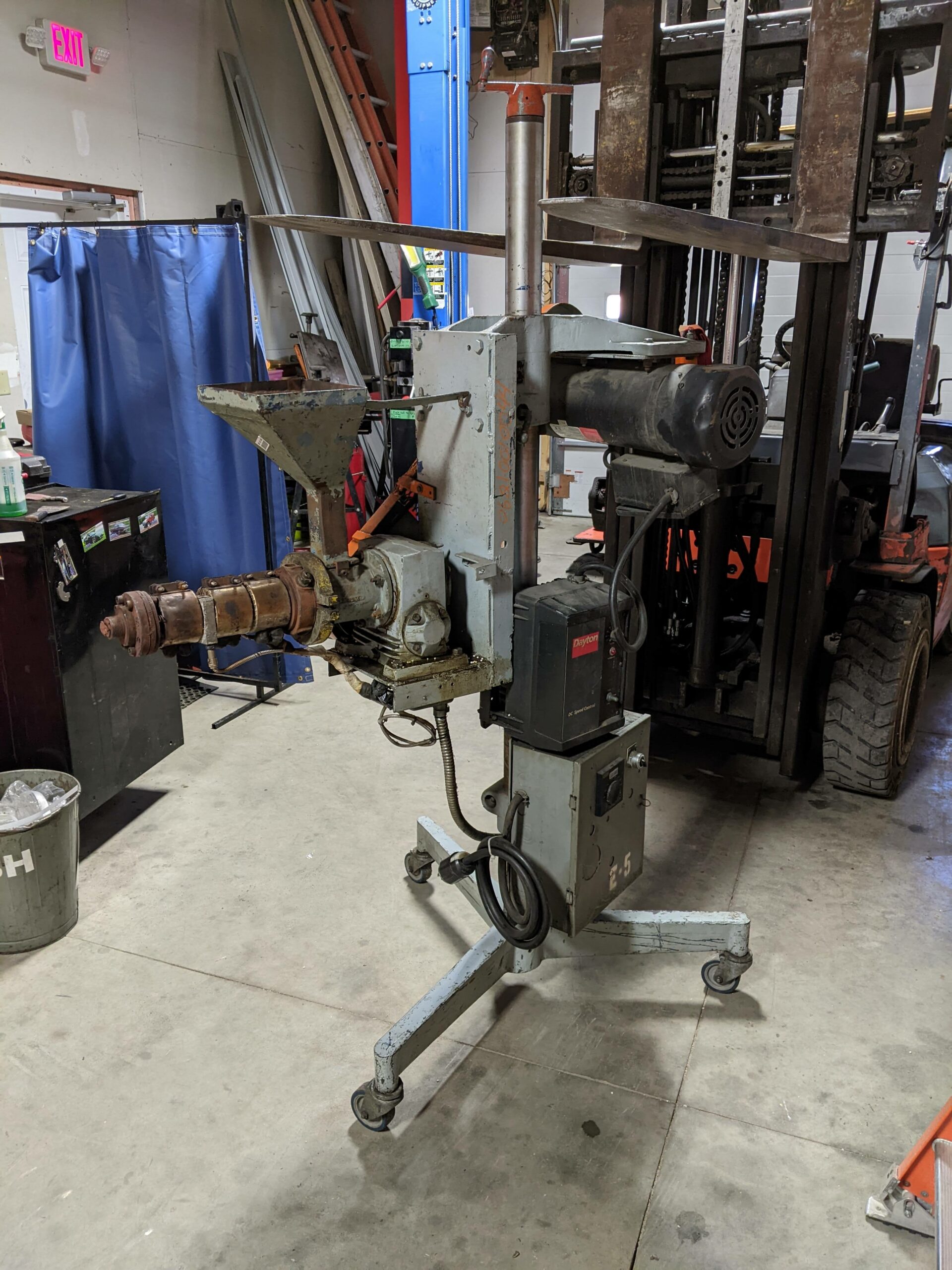
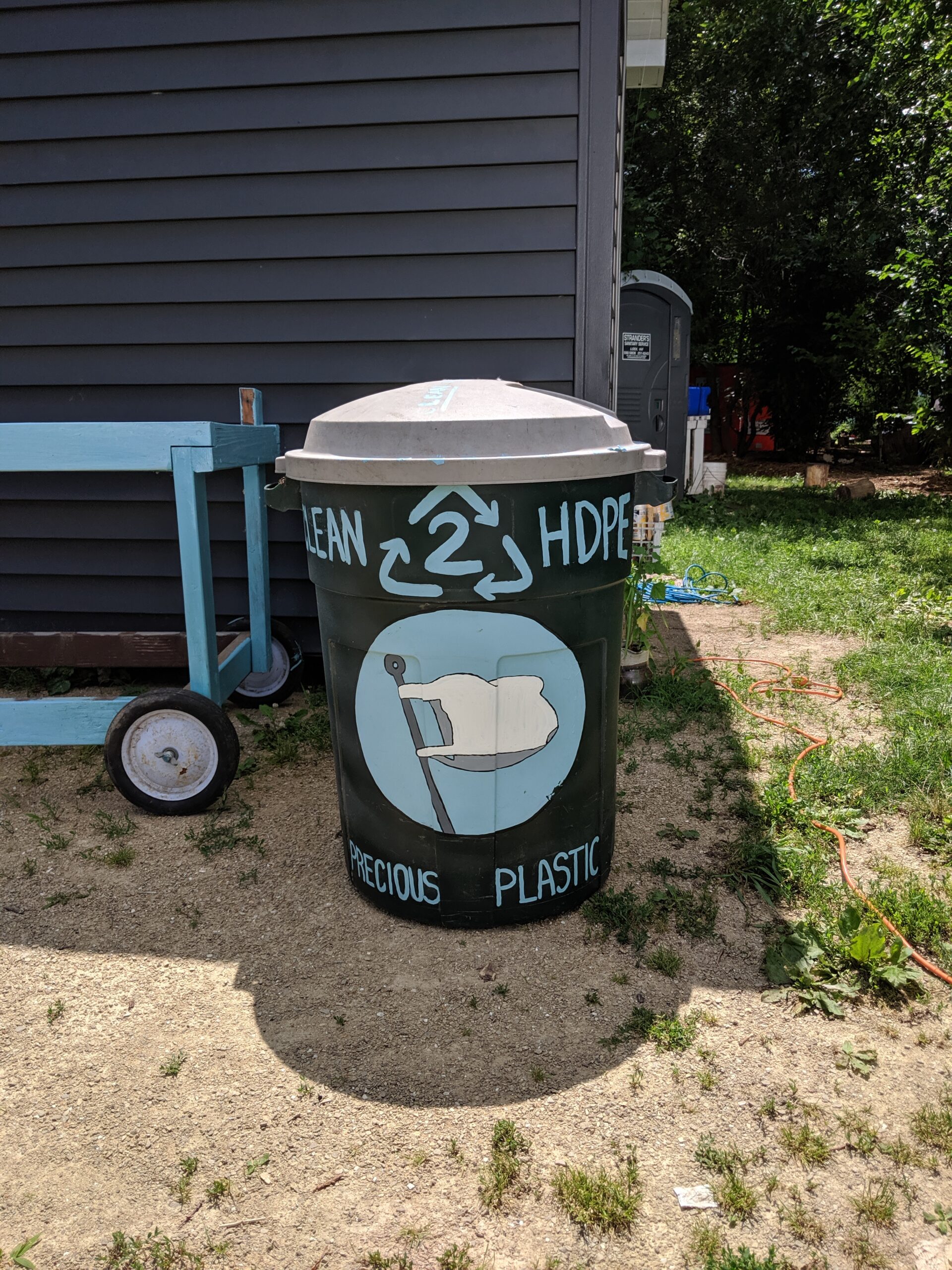
We’re excited to officially join with efforts at Precious Plastic to reduce plastic waste in our community directly – this project is supported by our awesome neighborhood association:
We’ll be working forward to re-use some industrial surplus plastic extruders with a target goal of producing dimensional stock (lumber shapes) that can be used for projects in the neighborhood. If you’d like to help with the construction of the machines, testing, or have ideas on generally useful continuously-extruded plastic products please reach out. We won’t be ready for material collection until we’ve had a chance to test things out and get a batch worked through all the steps!
The Backstory:
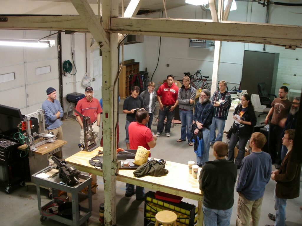
Our work recycling/reusing plastic began at the very first Sector67 meeting at our Winnebago St location in 2010 with Scott sharing his DIY benchtop injection molder used to create train wheels for a wooden train system following the Gingery design:
Injection molder at left, Scott red shirt at center.
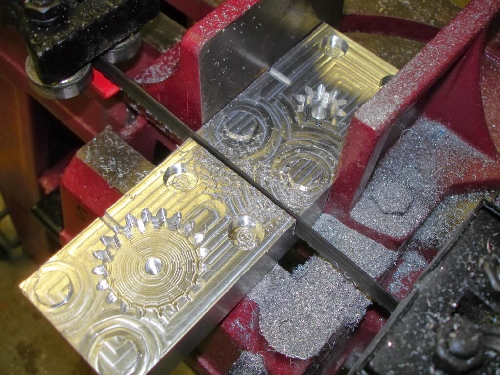
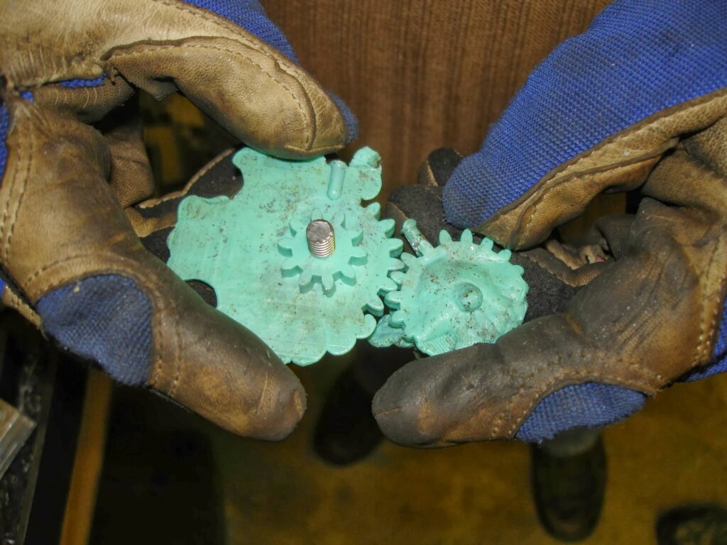
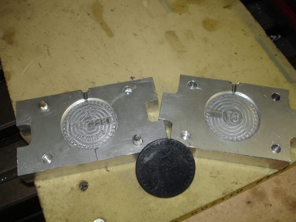
The very first thing ever machined on our CNC mill was a mold to manufacture gears from laundry detergent bottles:
Nothing like making both halves at the same time in an “all or nothing” approach
A little short shot (right) turned into a lot of flash (left) once the mold warmed up and separated under pressure.
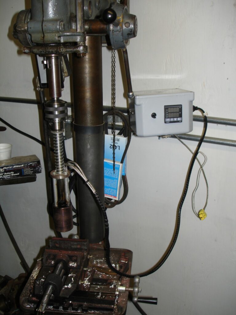
We went on to make a nicer system that went into the drill press:
And tried for more difficult molds/designs.
The challenge with injection molding is that it uses very little plastic and requires a lot of mold/demold time that’s normally fully automated with a production machine.
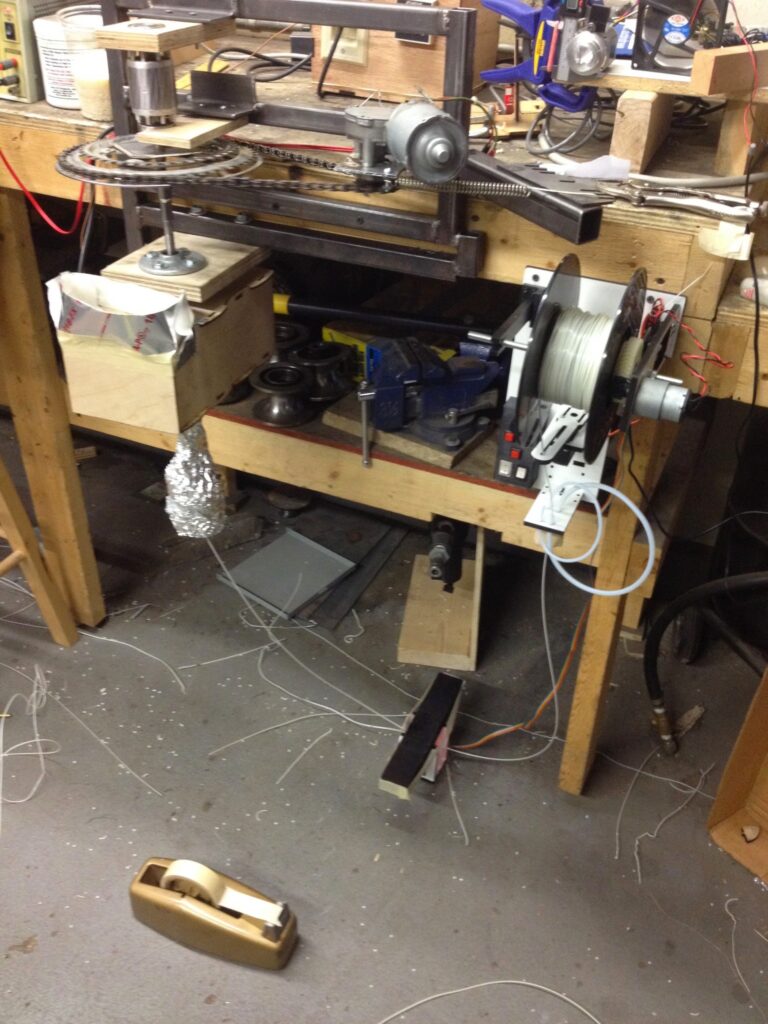
Bicycle parts and a wood drill auger bit at left (plus heaters) melt and extrude filament down, filament loops through a line laser (black bar at center bottom) and comes back up to a white winder and tensioner at right.
Making our own filament made sense when the raw stock was free, the issue being it’s unavailable in affordable small quantities as it’s really only an industrial product where manufacturers burn through it by the ton. The other difficulty is keeping the input plastic exceptionally clean, the 3D printer nozzle is only 0.40mm in diameter so even the smallest contaminants stand to block up the nozzle in short order. Ultimately this project was shelved with the wide availability of inexpensive 3D printer filament as machines dropped in price and demand grew.
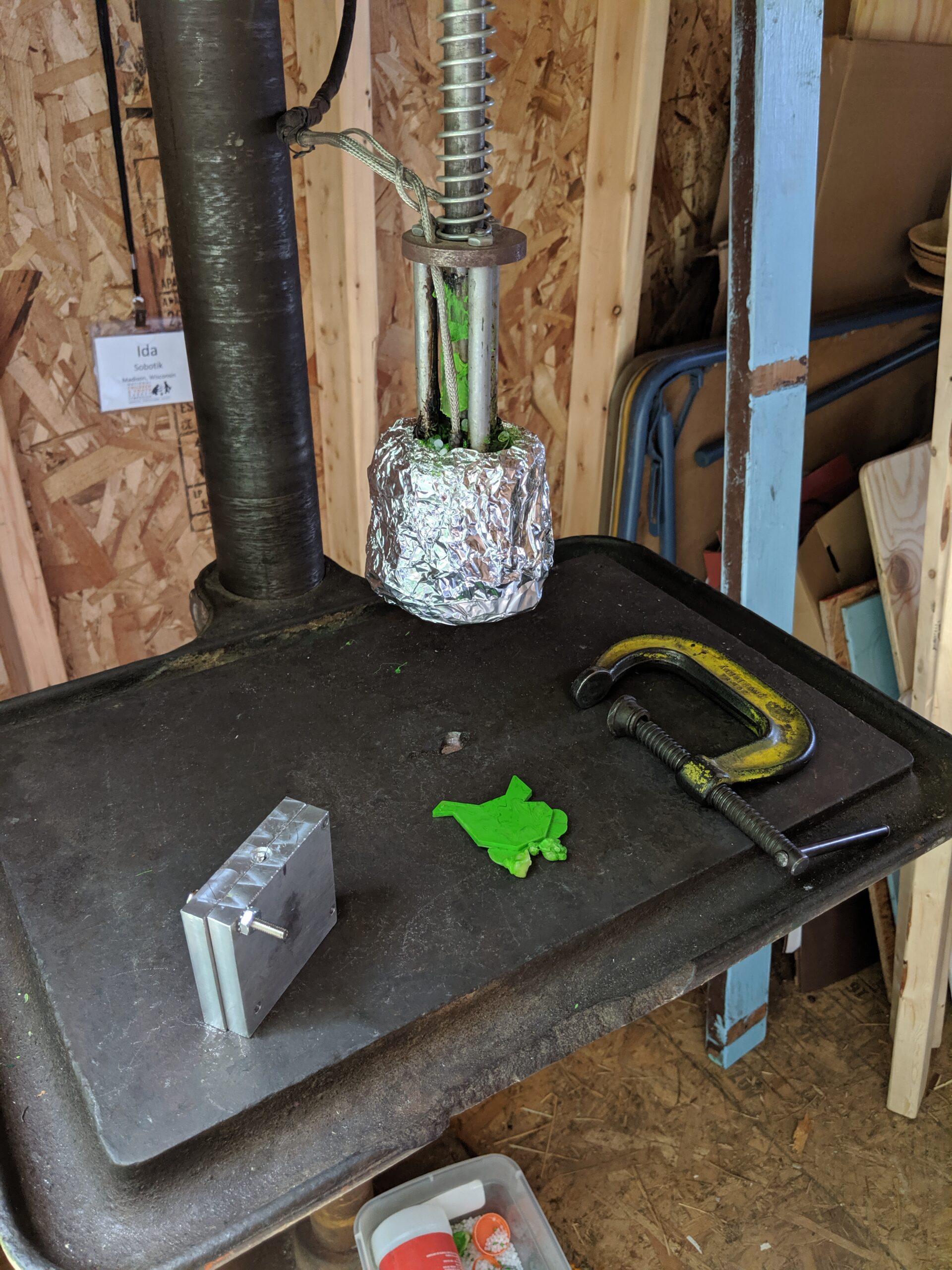
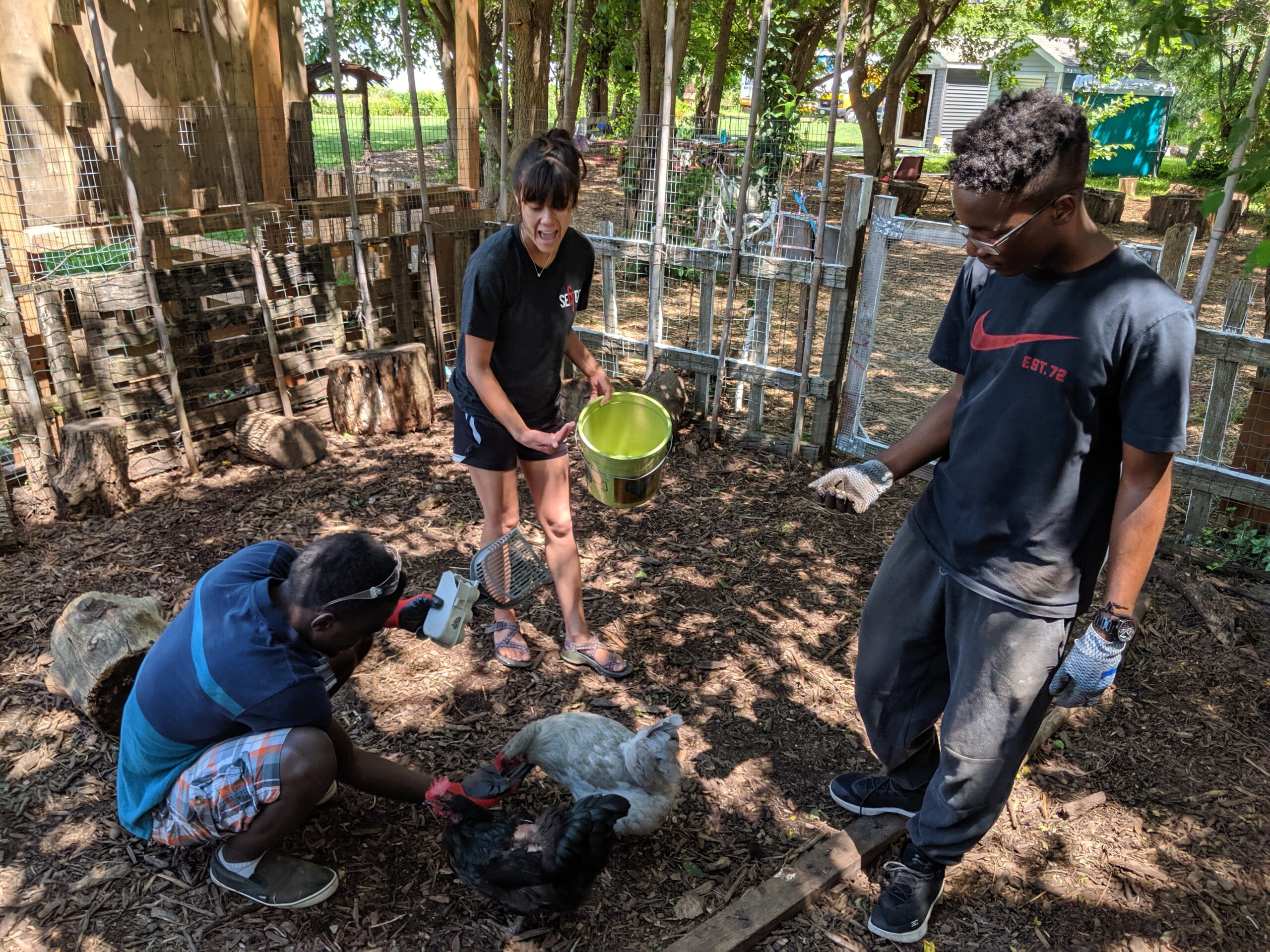
In 2019 interns Sadiq and David worked with Ida to build a standalone drill press molder for a pilot run of Precious Plastic at Troy Community Garden:
Gathering raw materials to make plastic chicken tiles!Inspired by the real chickens
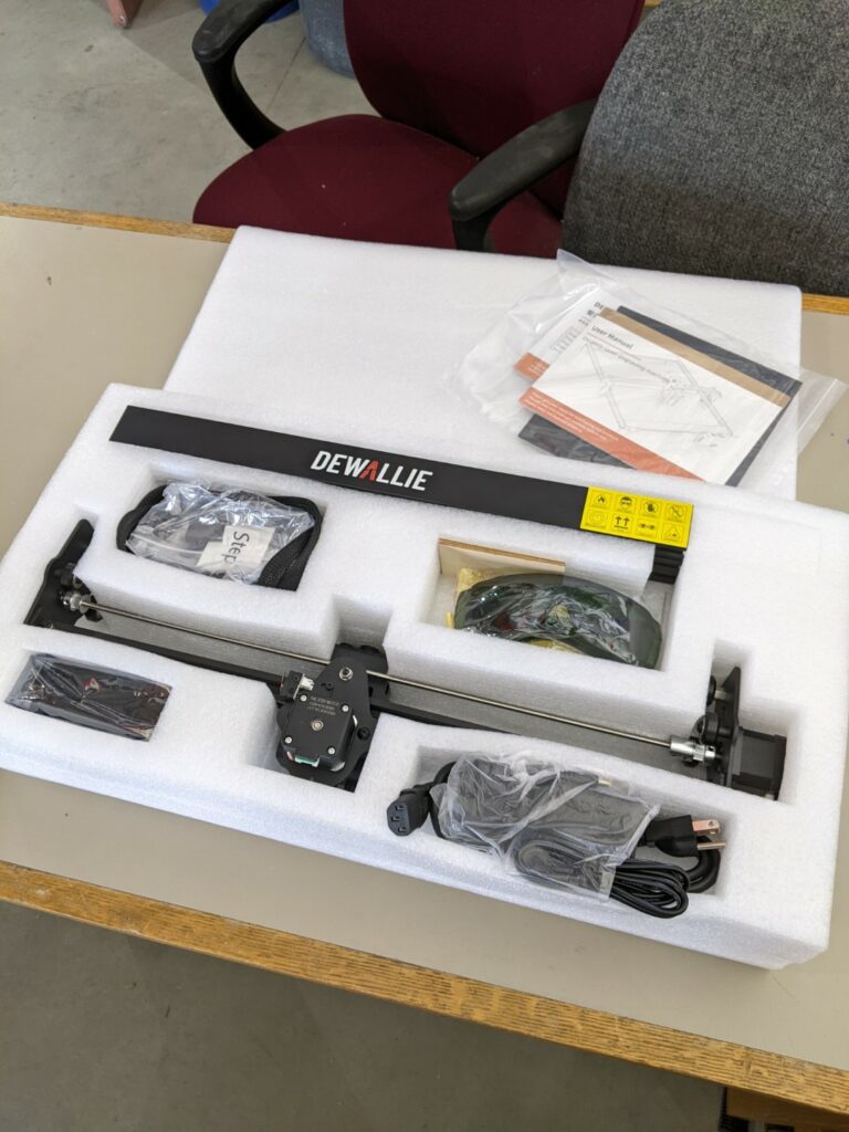
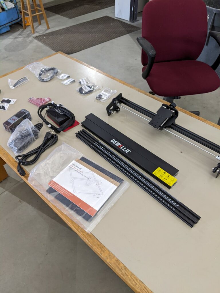
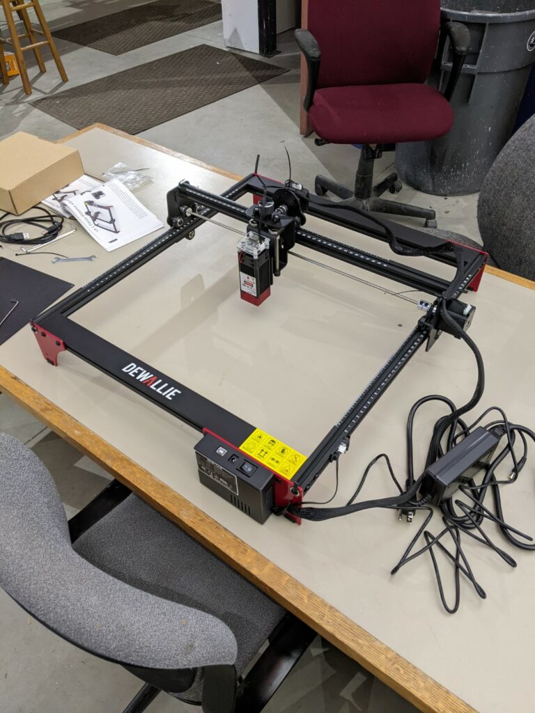
Dewallie was kind enough to contribute a 20W UV laser for us to review and test out. It’s the LA-2 version of the machine with a head rated for 3.8A @ 5V using Pulse Width Modulation (PWM) power control. It’s got a large work envelope of 400mm x 400mm which puts it over twice the size of the popular K40 CO2 lasers (200mm x 300mm). Opening up the package and it’s been broken down into just a few pieces for shipping with a 5 step assembly process:
Mostly assembled out of the box.The majority of the gantry comes preassembled with the X axis requiring no work at allFully assembled by someone with no experience in about 30 minutes
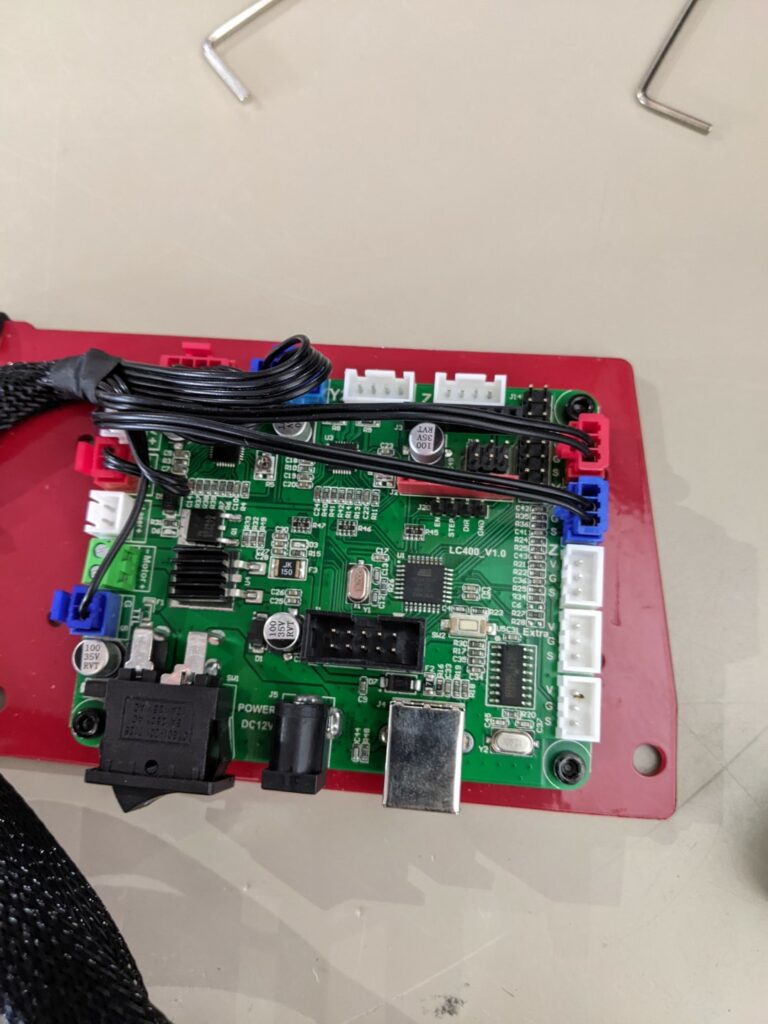
If you have a 3D printer this controller is going to look pretty familiar:
I bet you can drop an additional stepper driver on the open header but you’d still need to reflash the firmware. This looks like a pretty run of the mill GRBL Atmel 3 axis driver board but you’d need firmware or to reverse engineer the pinout to let you install a router motor and run it as a desktop router with a powered Z axis.
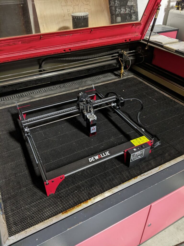
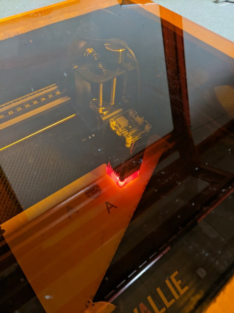
The easiest way for us to exhaust the laser was to put it inside our large CO2 laser, you’ll want to build a downdraft table or some form of fume extraction.
Once we had the machine constructed we needed to set up some better shielding. The machine comes with OD3 glasses, which when coupled with the nozzle/air assist cone they’re supposed to provide adequate reduction in brightness but we wanted to fully enclose the laser and provide a viewing window. $17 and an order to J Tech Photonics and we had a 12″ window with OD3+ protection to keep us a little better protected. It makes a world of difference in brightness:
Factory provided shield but you can see the amount of (bright!) indirect light leakage. They provide laser safety glasses but we wanted something that was easier to use/keep in place.With the OD3+ acrylic window in place
Onwards to some test engraves and cuts. To frame expectations this is a 20W 445nm laser, it’s not going to cut like our 150W CO2 laser but it carries a correspondingly lower price tag and a minimal set of additional equipment required (no chiller/water cooling, multiple power supplies, etc). The machine does well running slowly (<10mm/sec for wiggle free vector cutting and engraving) and will need multiple passes to cut through plywood. Their sample materials give you a quick sense of what to expect: anodized aluminum tags and sheets for engraving, cardboard/tagboard, 2mm plywood, etc.
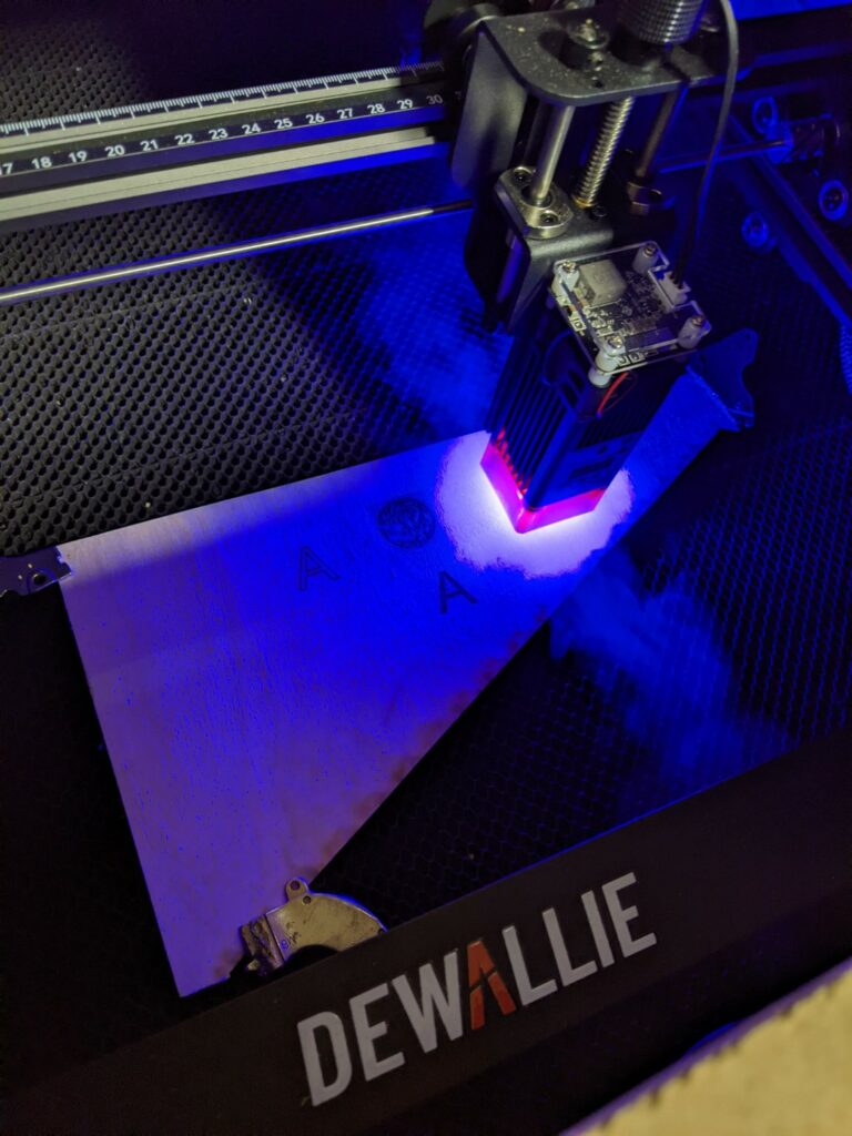
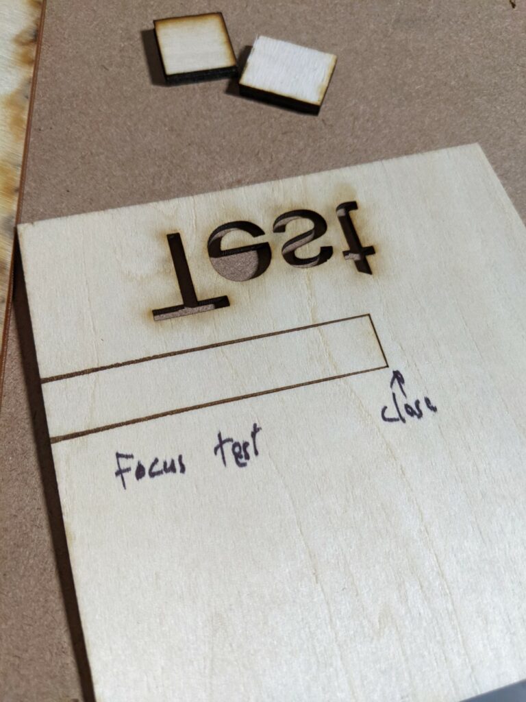
To start off make sure you test and set the focus. An easy way to visualize the focus height is to put a piece of thin wood under the laser and prop up one end to form a ramp. Have the machine cut a line and you can see where the laser is in focus based on how small the line gets:
The right side of the cut was closest to the laser output, you can see how the beam widens as it goes left showing that it’s losing focus.
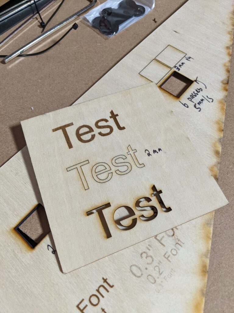
The thin sample plywood they provide cuts and engraves well:
Provided 3 layer 2mm plywood cut well.
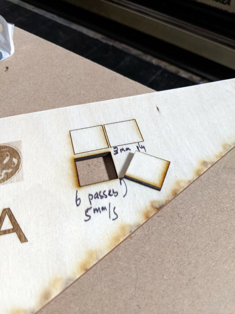
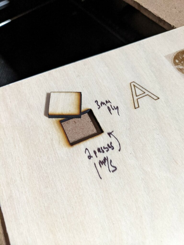
We had some thicker 3mm interior/cabinetry plywood that it had a hard time cutting through:
It knocks out about 0.75mm per pass at 90% power running at 5mm/secReducing speed doesn’t seem to be a good strategy, it results in a lot more char/burning then taking many small bites.
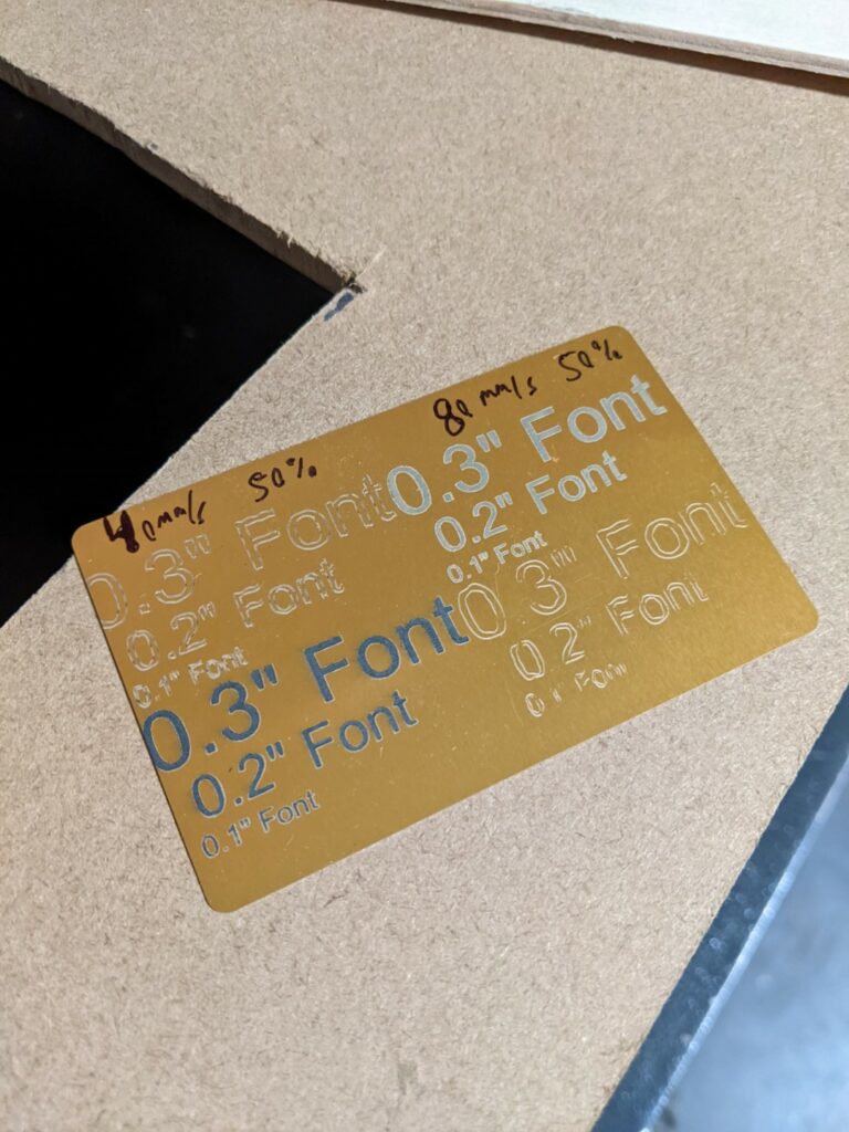
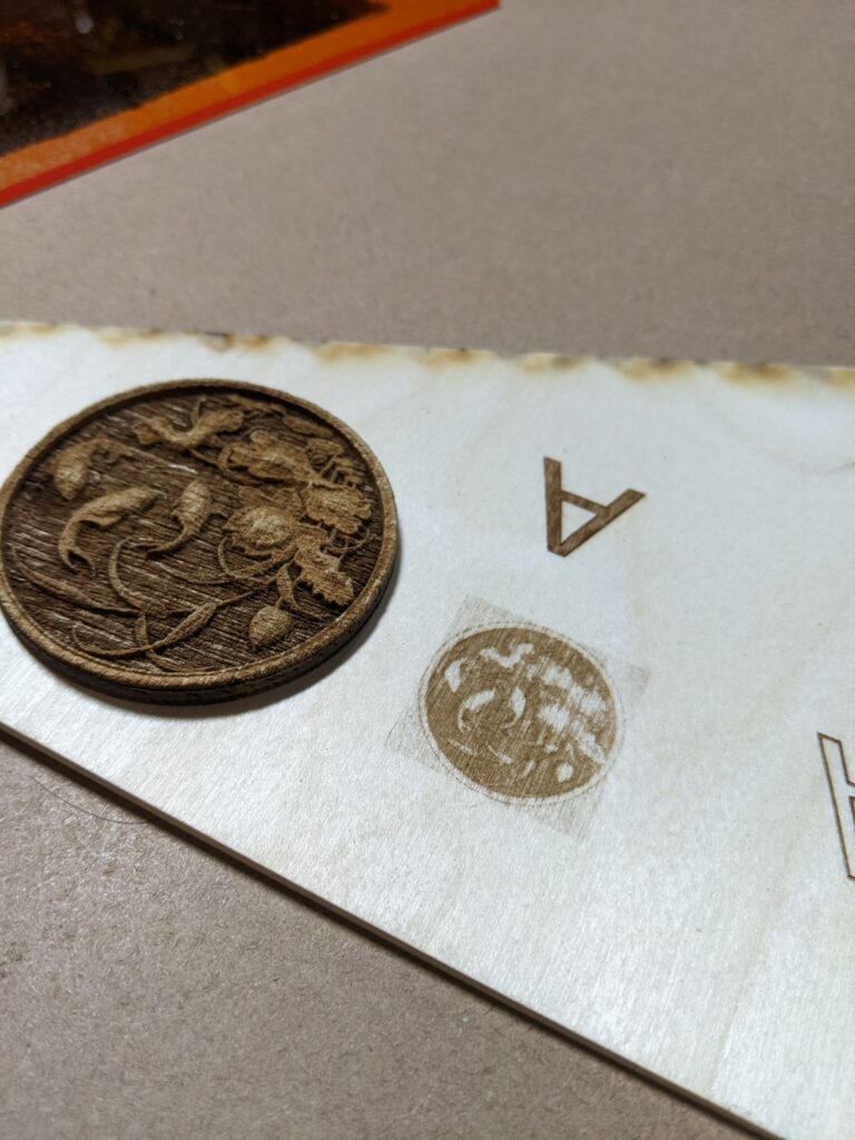
It performs very well at engraving anodized materials:
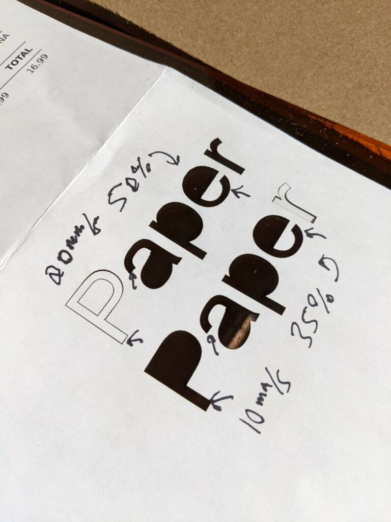
The filled areas came out nicely, to demonstrate some issues you’ll see shortly I left high speed line engraving turned on and you can see the gantry has a lot of flexibility/wiggle at speed resulting in poor quality vector engraving. The resonance seems to be mainly in the Y axis which is what we’d expect there’s a lot of mass we’re hauling around in the X axis that results in belt flex. Cranking up the belt tightness and putting in gusseting/stiffeners would help here. Take a look at the arrows below to get a better sense of the issue, you can see at 20mm/s the paper shows the resonance but when dropped to 10mm/s it’s almost totally gone, paper is a great way to visualize this because it’s cuts so easily.
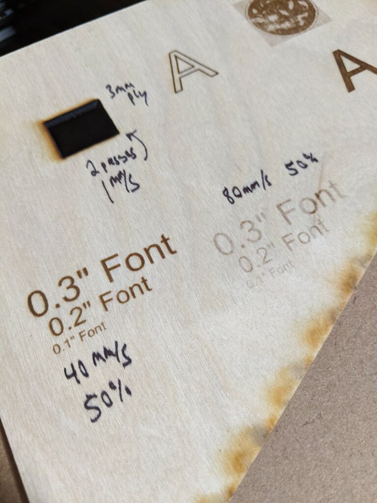
Where these lasers excel is at raster engraving things
The 40mm/s 50% power engraving came out clean and consistent, no stepping from engraving in both directions at all. It looks a little blurry but that’s camera focal plane.
Where performance falls off is engraving at high speed (>80mm/s) detailed objects. The onboard controller is an Atmel microcontroller (Arduino) so the command rate is limited. I’m sure the laser can fire quickly but the controller isn’t up to the task like a much more expensive Digital Signal Processing (DSP) laser controller. Admittedly the DSP controller would cost you more than this entire laser so its far from an apples to apples comparison but it’s worth mentioning:
At left is a grayscale PWM engraved koi pond image from our 150W CO2 laser in a single pass, at right is an attempt at the same file on the UV laser at about 1/3 of the speed.
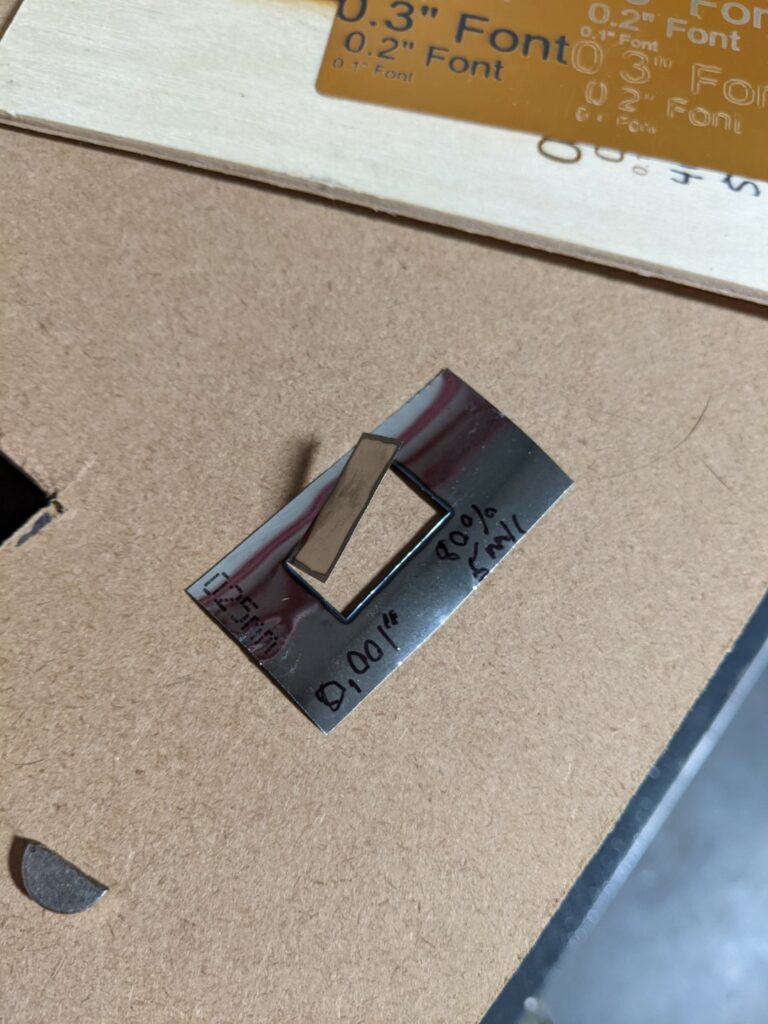
Where we had some fun was taking advantage of the small spot size and wavelength to cut 0.001″ steel shim stock. It is possible to cut steel but not mark it without dying the surface to improve absorption.
80% power 5mm/sec cutting through 0.001″ steel shim stock
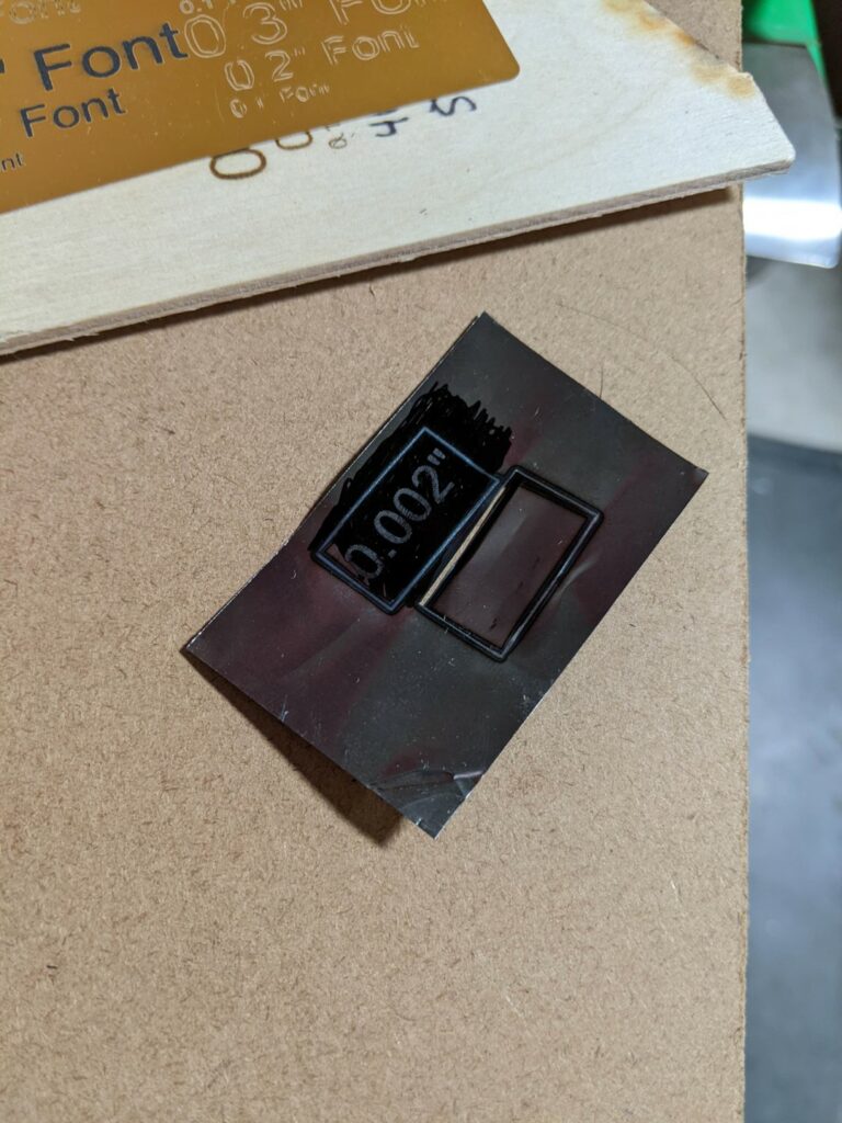
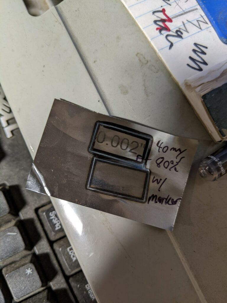
It was able to mark Sharpie coated steel as well, the black pigment increases beam absorption and assists in the heat transfer rather than reflection.
Sharpie allows the beam to be absorbed into the surface rather than reflected, we were unable to pierce 0.002″ thickness material though so it’s very limited in capacity.After cleaning the Sharpie dye off with acetone, also interesting is the heat affected zone retaining dye at the perimeter of the upper cut. It looks like the Sharpie can take a heat set and more readily resist solvents.
Overall for $310 you won’t find a much more capable machine, the 400mm gantry gives you a large work surface and it’d be possible to run this machine off a battery and do some outdoor/portable engraving since there’s little to bring along besides a laptop and the gantry itself. The downside with the 445nm UV laser wavelength is the heightened eye hazard working in a visible light frequency that can go through glass/glasses/corneas to damage your retina permanently – be careful!
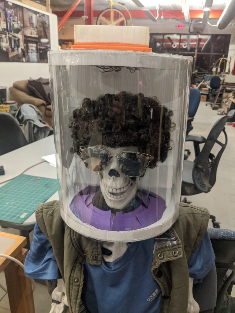
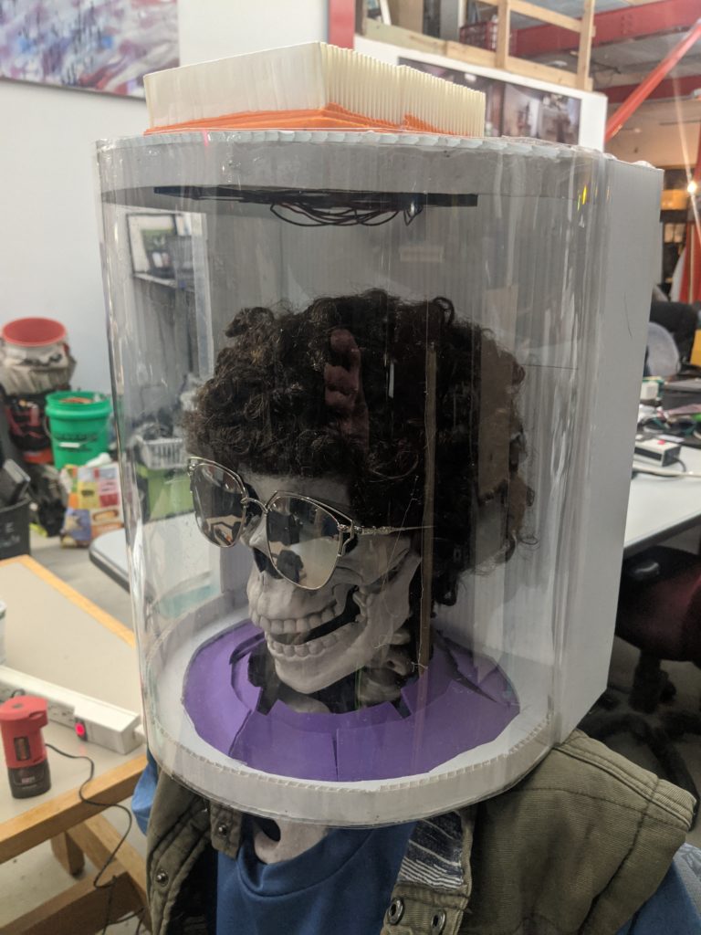
We’ve been noodling on a variety of Personal Protective Equipment (PPE) we could help with. There’s been a big push internationally to try to replicate existing PPE like 3D printing N95 masks and attempting to clone forced air breathing systems – the challenge with these efforts is they’re starting with an item that was designed for mass manufacturing and trying to go back to DIY fabrication methods. Jim went back to the drawing board to try to come up with the least expensive off the shelf parts PAPR he could come up with:
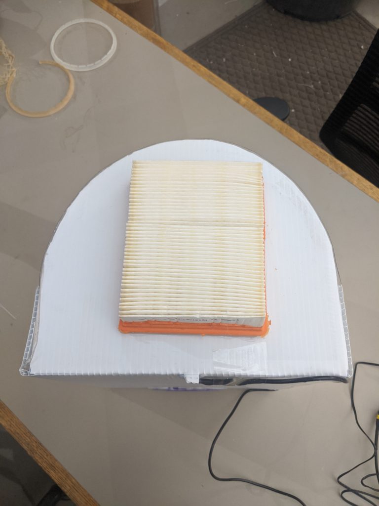
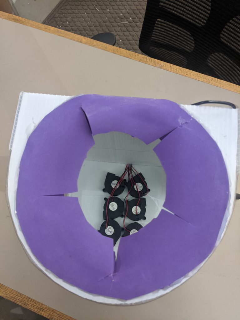
The basic components are a political sign, a 2 liter bottle, 3D printer centrifugal blower fans, a power tool battery pack/adapter, and an off the shelf HEPA rated vacuum cleaner filter. While this isn’t the most beautiful creation, it fits the basic requirements of a PAPR in filtering air around your head and keeping contaminates away. One of the things missing is the hose – it’s hard to source breathing rated hose and nailing the flexibility and smooth interior walls is difficult. If you use off the shelf hose it off-gasses plastic additives forever, it’s what keeps the hose flexible.
We’re using:
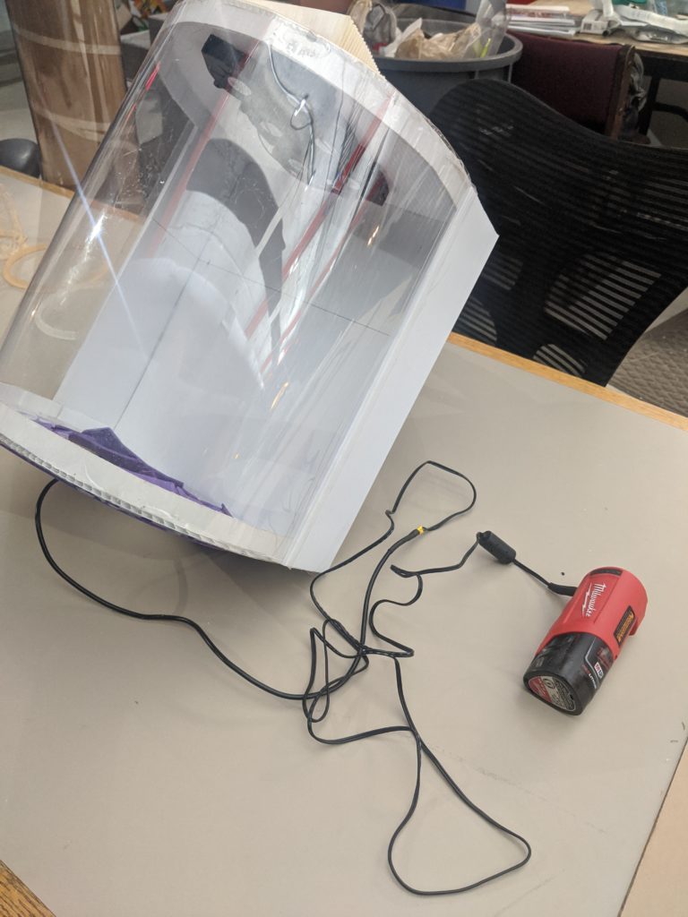
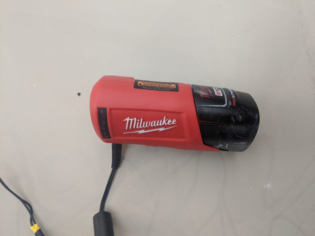
A Milwaukee Tools M12 heated jacket adapter as a convenient way to convert the bare pack into a 12V power source (bonus feature, you can charge your phone while you’re using it! /s) You can also run an M18 pack if you use 24V fans with this adapter.
Coroplast, this is cheap polypropylene or polyethylene corrugated sign board, you can find one curbside (look at it this way, you’re still advertising for them) or pick up a sheet from Home Depot to make a ton of these from. Any fabric or compliant foam works for the gasket around the neck.
You can purchase PETG as a sheet/or in a roll form as PVC, or you can use a clear 2 liter (or larger) bottle, you’ll need to adapt your coroplast cutout to match your “window” size.
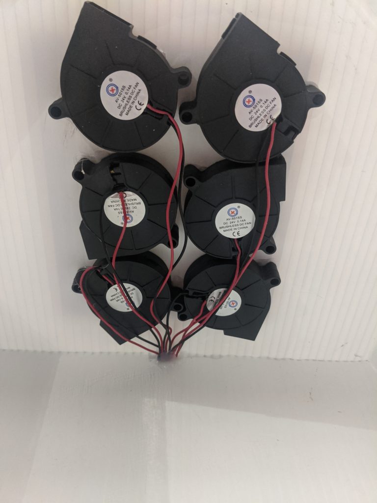
We chose fans we had handy, these are 50x50x15mm 3D printer hot end cooling fans, they’re commonly available in 5V/12V/24V. We used 24V fans as they’ll run on nearly any power tool battery you have available. You cannot use standard axial square fans, they will not drive enough flow with any restriction or backpressure from the filter or user. Don’t used brushed DC fans, they generate ultrafine carbon dust you don’t want to be breathing.
Filters are widely available as long as you don’t search for the same thing everybody else is – don’t look for N95, look for HEPA vacuum filters, Miller welding PAPR filters, etc. You need to get something that’s rated at 99.97% filtration HEPA, not all HEPA filters are the same rating. Ideally purchase a PAPR filter, they’re NIOSH (breathing) rated, but a vacuum cleaner filter will still carry a recognized rating. Vacuum filters can’t be used for a mask because they’re too hard to breathe through, fortunately you have a fan doing the breathing for you.
Main improvement would be to use a hard hat as the frame so it transfers the load off your shoulders and centers on your head. We wanted to use off the shelf and widely available materials but there’s obviously room for improvement.
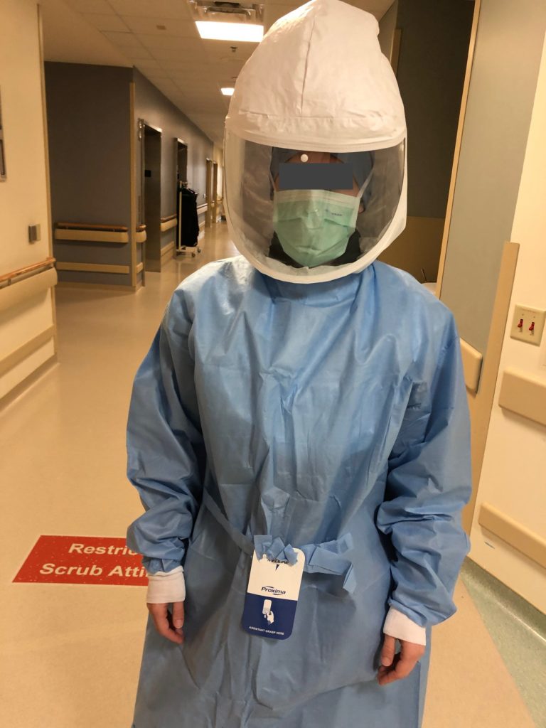
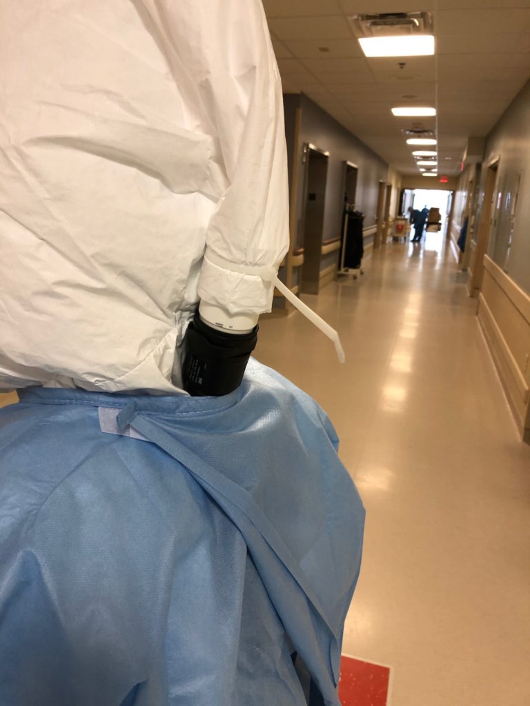
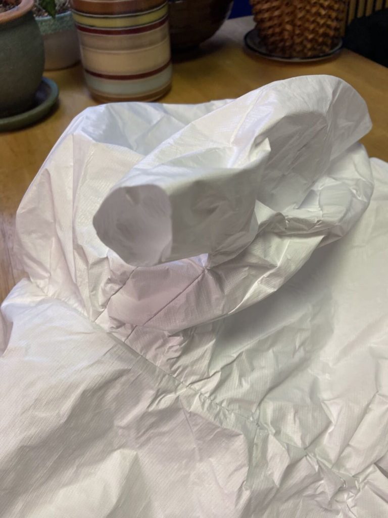
Continuing our pandemic saga, a local hospital needed a PAPR hood adapter to transition from a plastic “cloth” hood to a 3M Adflo PAPR hose. They’ve been taping the corrugated hose to the plastic hood flap but they need to be able to reuse the hood and sanitize the hose, all of which are a lot of work that can be avoided with a simple cleanable adapter.
The easiest approach would have been 3D printing these, because the hood is under positive pressure any leakage should be pushed outwards. There are a few issues though:
The only printers we have available are FDM, meaning we’re printing them standing on end so the layers are aligned with the tension load of the hose/hood, the potential failure mode is a shear across the layer which would be catastrophic
FDM printers have high porosity, much larger than the particulate we’re trying to block. Although when the hood is powered it’s under pressure, there may be exposure to a hazardous environment when the blower is off (power runs out, it’s been removed for storage/etc), meaning we could be absorbing particulate then blowing it into the user’s helmet when it’s powered on again
3D printing at accelerated speeds yielded about an adapter every hour and a half, we needed to make at least 32 of them and possibly more with a goal of a few day turnaround. Although we have a large farm, this is still a lot of print time and post-print cleanup
3D printing leaves a lot of sharp/hard edges from stringing and layer to layer bonding. We don’t want to have our adapter damage/abrade the hood or we’re causing more harm than good
We love 3D printing, but it’s sometimes not an appropriate application beyond prototyping. . .
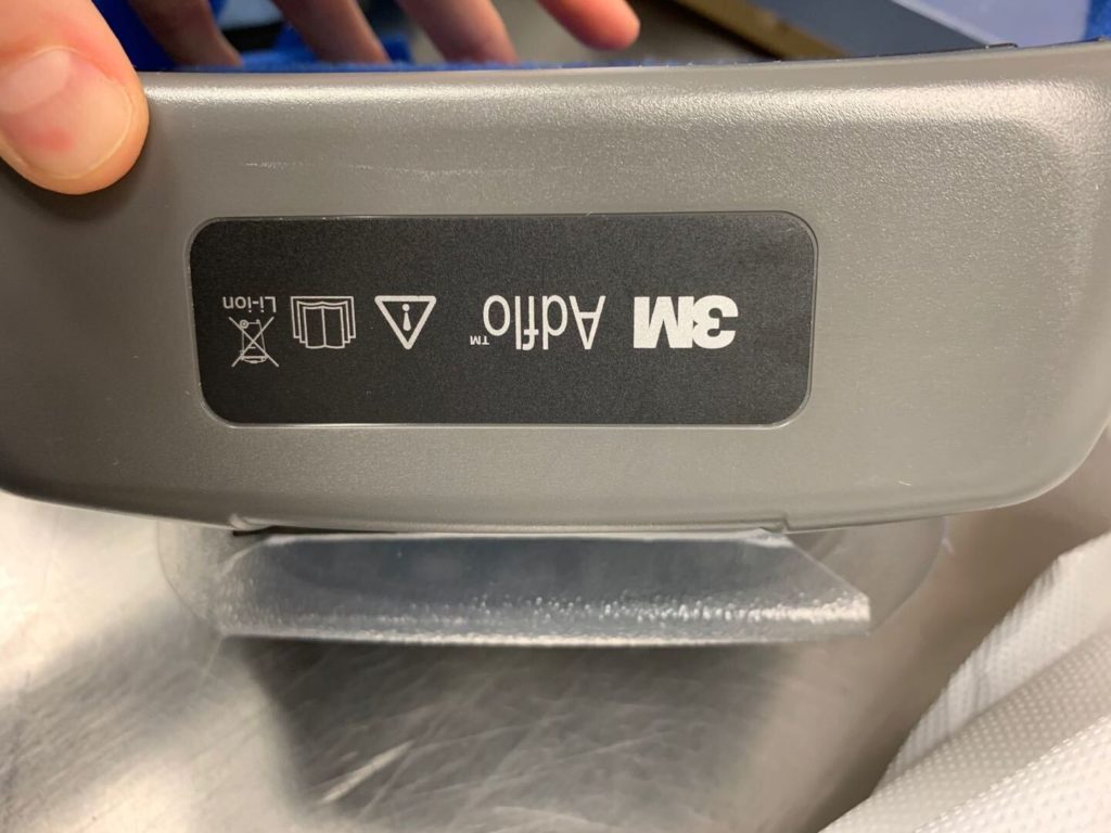
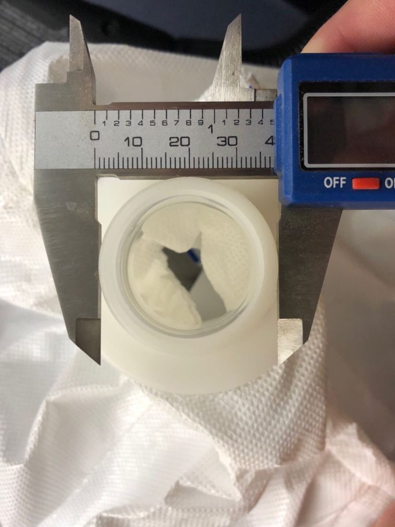
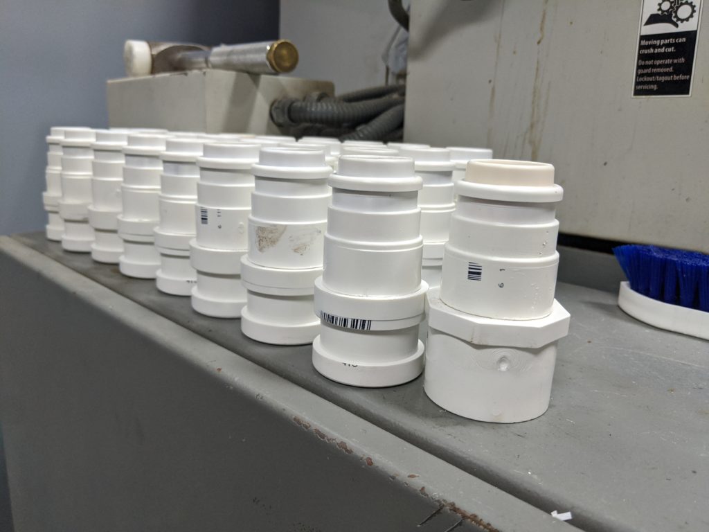
The first step was trying to ascertain the scope of the challenge – quantity, turnaround, cost, etc. In this case the desired cost was zero, quantity high enough to merit some optimization, and the turnaround fast. We tried to hunt down a model and once we figured out the model of the hose (3M Adflo) it was quick to find this adapter on Thingiverse. The hospital didn’t have a working caliper but via some pictures with a reference ruler in frame we were able to confirm the dimensions were in the ballpark:
The next step was brainstorming available materials. The OD and ID matched up reasonably well with 1-1/4″ schedule 80 pipe, but on a weekend it wasn’t feasible to pick up thick wall plumbing pipe as all the true plumbing supply stores were closed. We stumbled around for a bit until we realized that a 1″ schedule 40 pipe ID was still great, but if we glued a coupler onto the outside it’d get us up to the OD ring size we needed to get the hose coupler to lock.
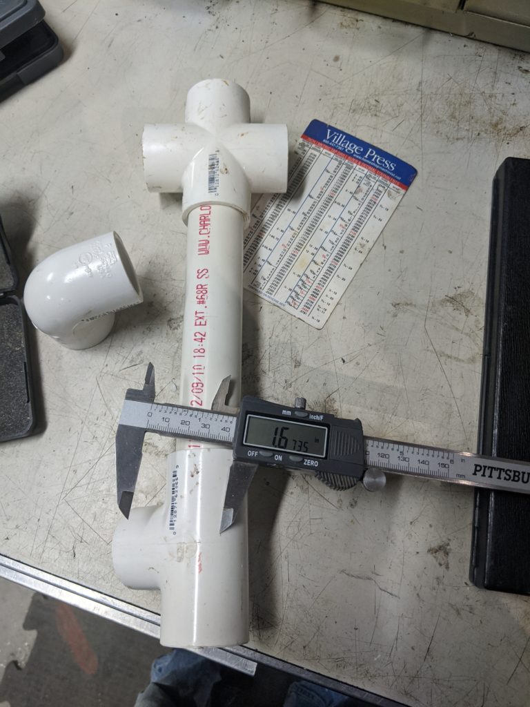
A run to the hardware store yielded plenty of fittings:
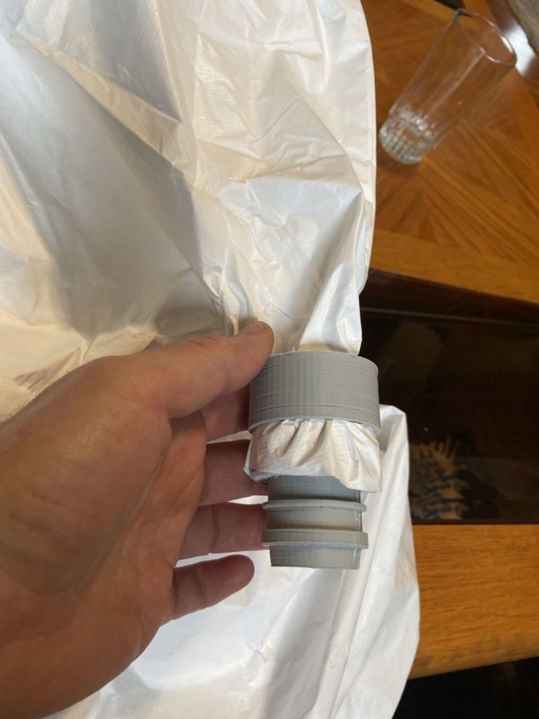
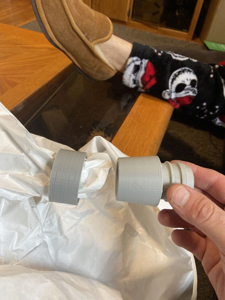
We weren’t sure how to couple to the hood, we thought a slip ring to a taper lock would work well and wouldn’t require tools or any other supplies so we printed a sample:
The parts locked together well so we we moved to a PVC version next on a manual lathe. The PVC taper was too slippery to lock on the fabric, so we went back to the drawing board to eventually settle on a zip tie approach.
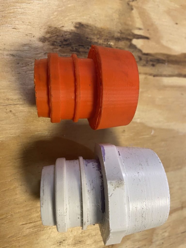
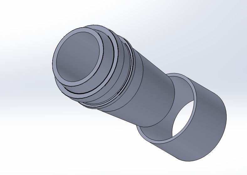
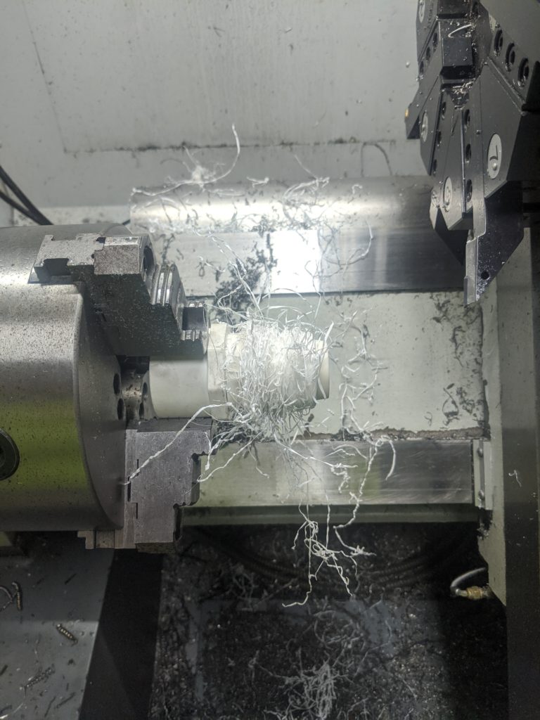
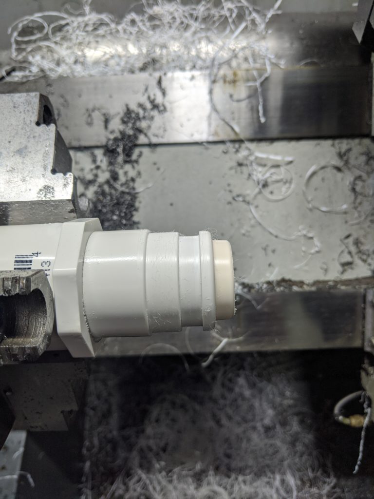
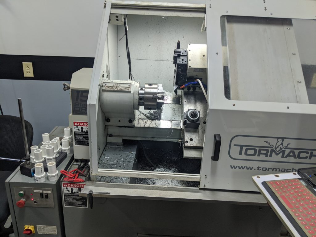
Next step was to generate a file in Fusion360 that we could use to run our Tormach 15L CNC lathe to make a prototype. Fortunately PVC cuts well and we had hammered out a practice adapter on the Adflo end in about 2 minutes. (starts off a little furry, chipbreaking plastic is hard to do grabbing a thin pipe). This was version 5 for anyone keeping track:
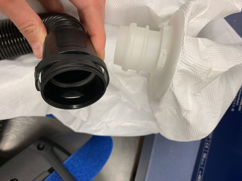
This part was tested on the PAPR hose, unfortunately these are in such demand that they can’t be taken from the hospital for fit so we have to run prototypes back and forth. The tapered nose was determined to be a little too big so we revised it and also dropped the narrow ring, it wasn’t serving any purpose on the coupling.
After 7 versions, we were ready to make a pile of them, easy enough just rinse and repeat right? We forgot one of the annoying parts about PVC pipes – the socket joints like to push out if you don’t hold them together tightly after gluing them, the coupler has a reduced center to keep you from pushing the pipe in too far, and the solvent needs to flash off for a least a day before we start cutting them or they turn into melted plastic on the lathe!
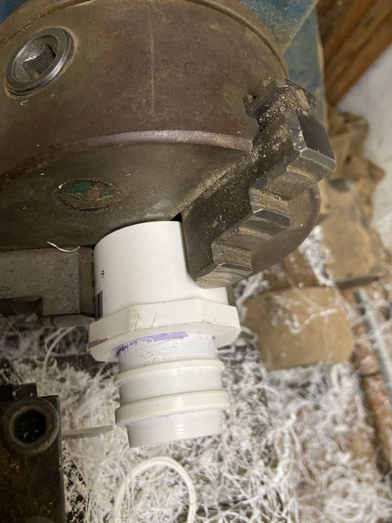
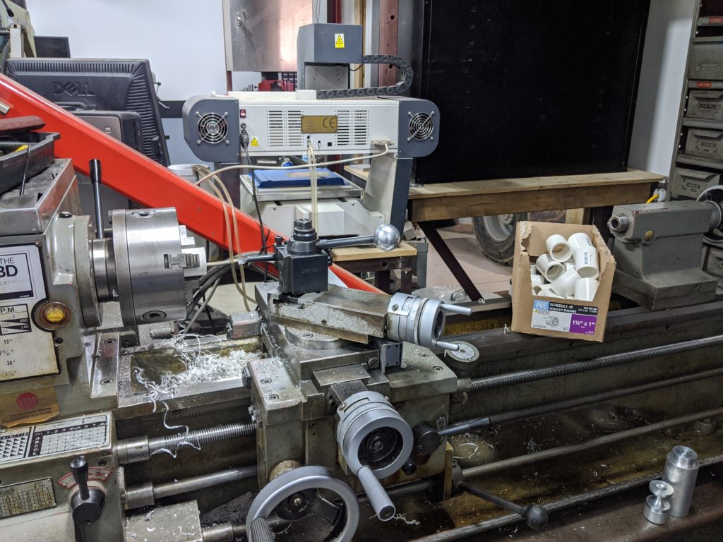
Onwards to a resolution, the first to set up the manual lathe to blast out the coupler center ring:
Of course PVC pipes aren’t meant to be turned/centered, so the middle isn’t quite in the middle of the coupler making an interesting time trying to turn them, basically we inserted the boring bar to the middle of the coupler, then brought it straight out until we cut a band in the middle to remove enough of the pipe stop.
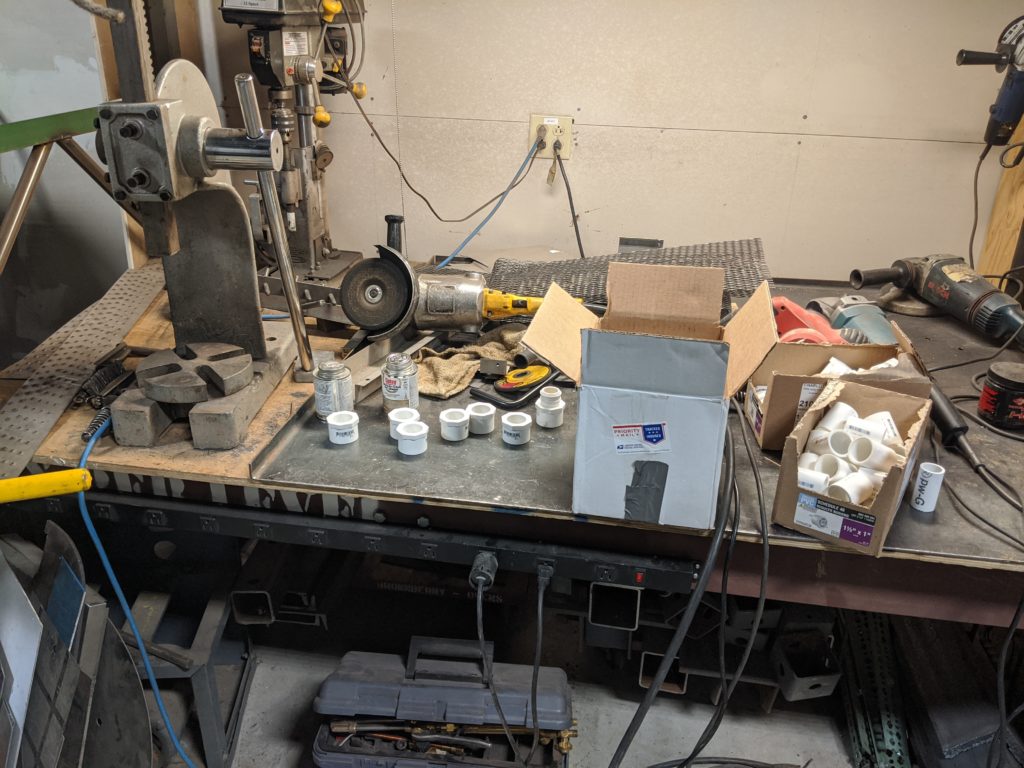
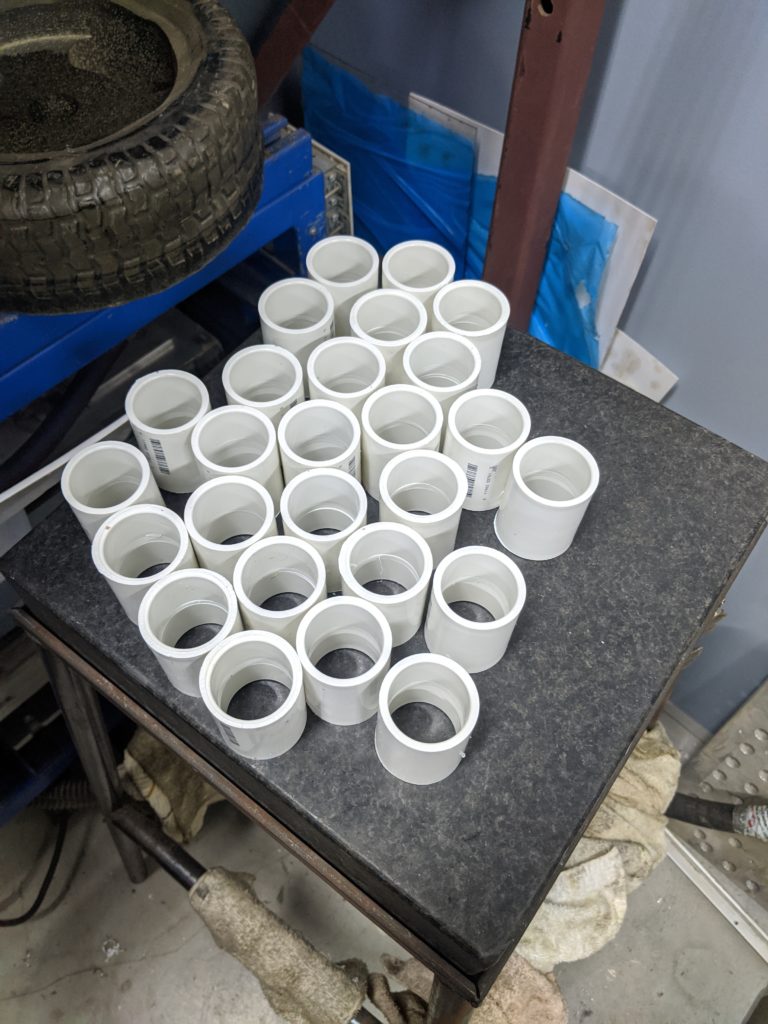
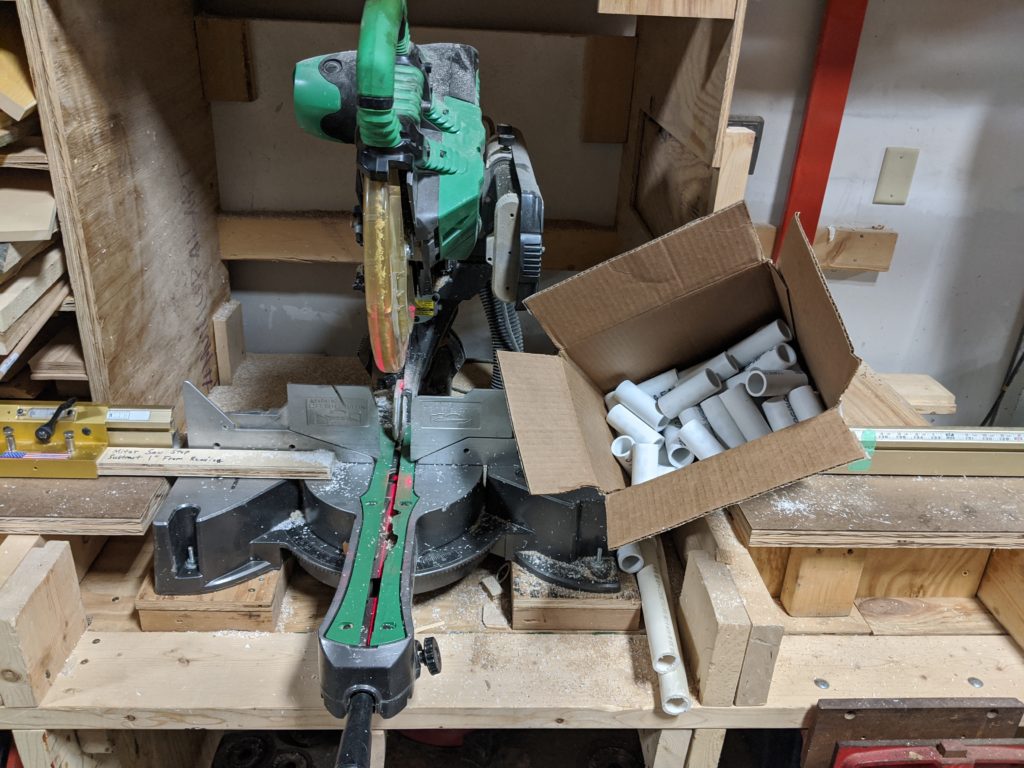
Then we needed to batch out enough pipes to length on the circular saw:
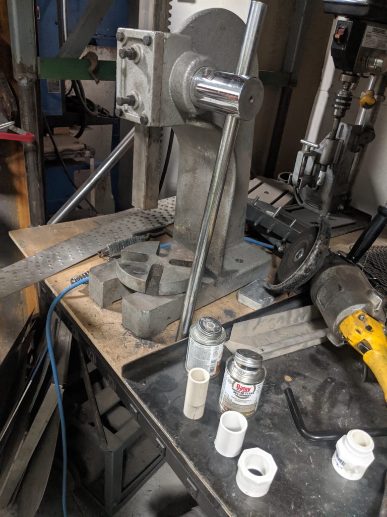
Then we brought it all together with an arbor press and a lot of clear primer/cement
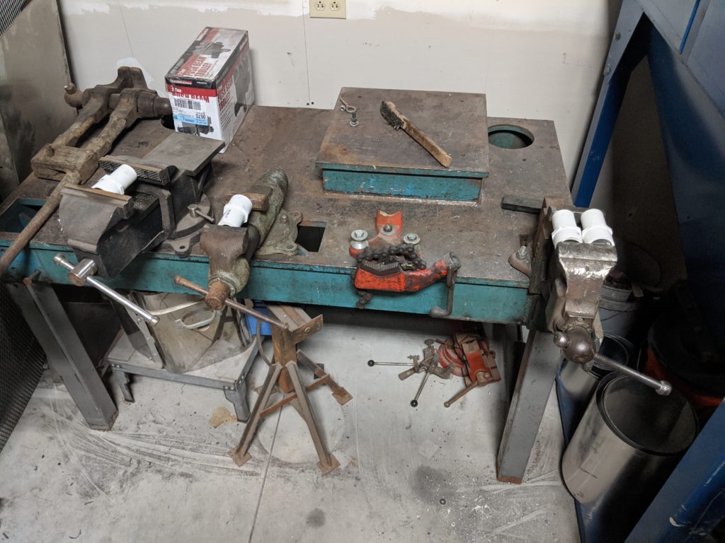
After gluing them went into a vise to hold the pieces together long enough that they were set in position, it turns out having 6 vises in the welding shop is sometimes very handy.
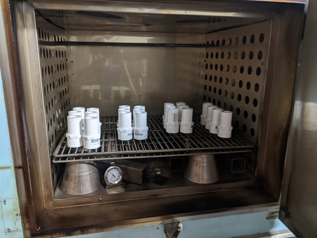
The next step is to flash off the remaining glue in the industrial oven at low temperature, doing so we can accelerate the drying rate to just a few hours.
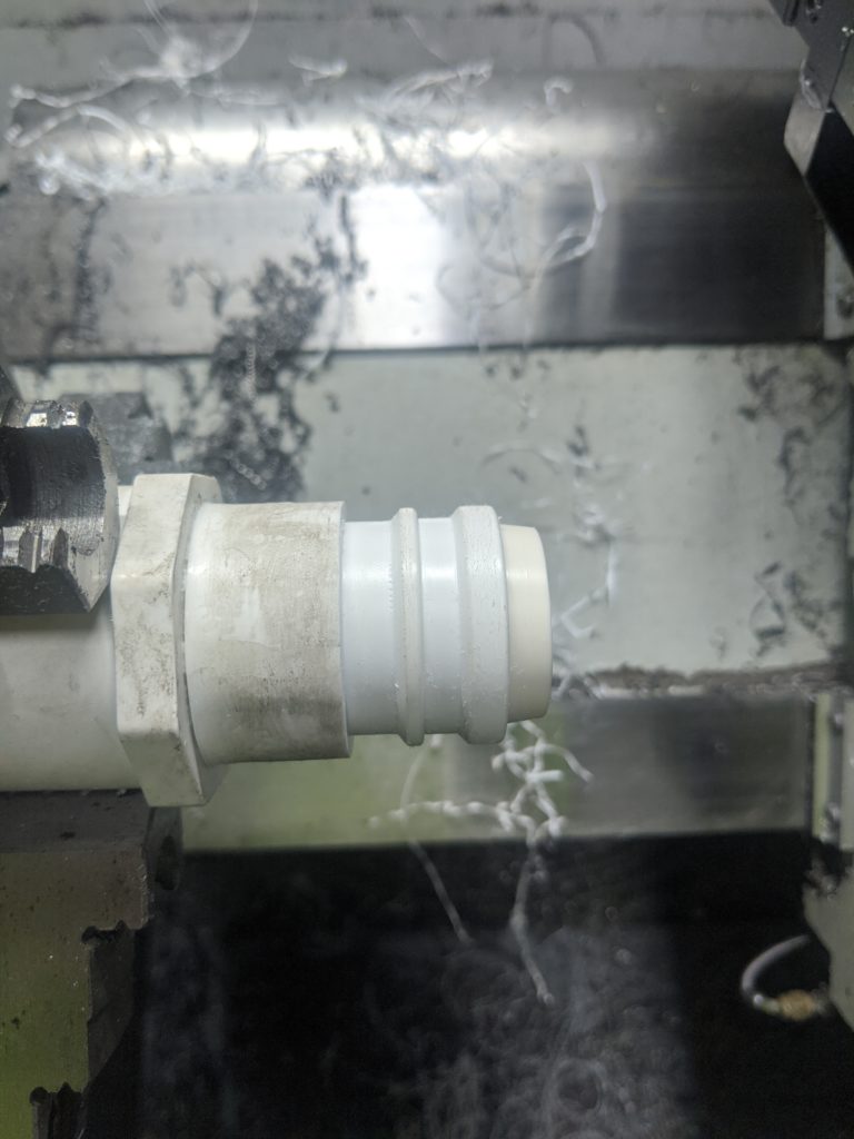
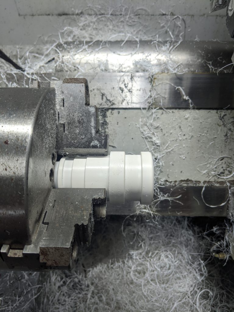
Then it’s on to the CNC lathe to first cut the hose coupler side
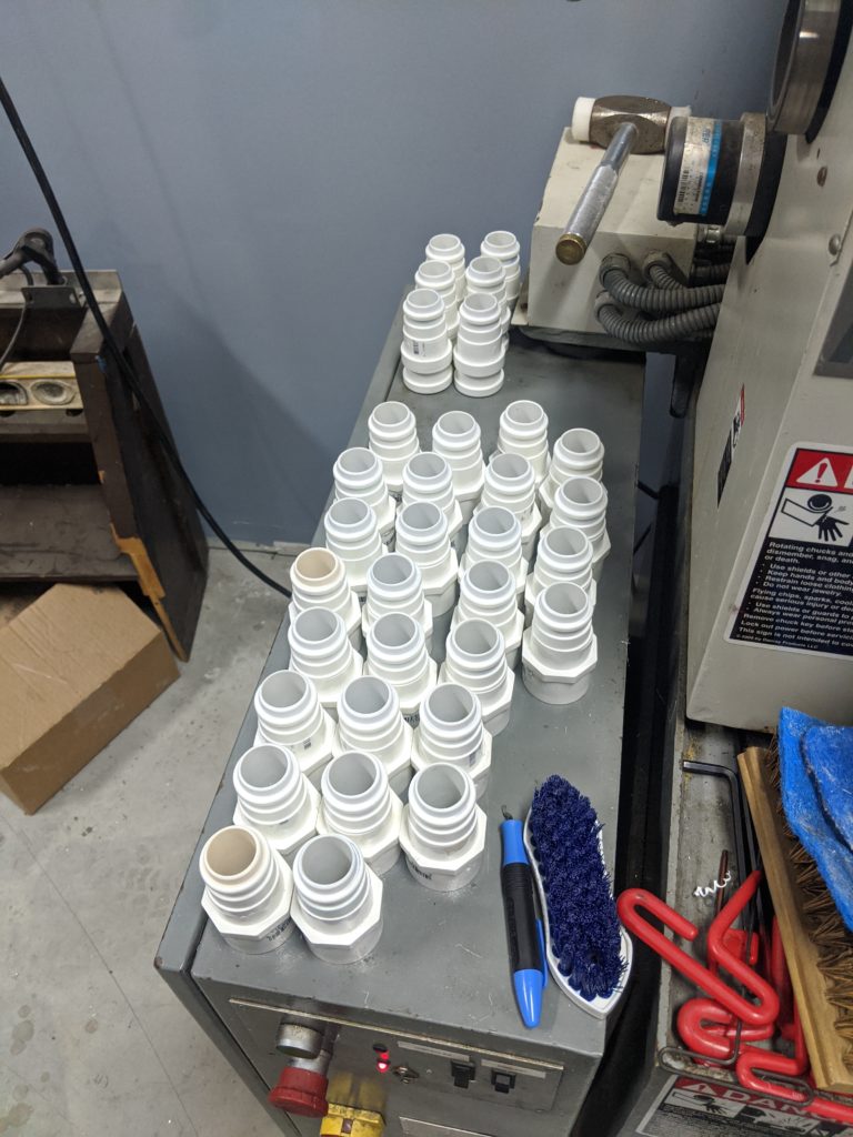
Then flip to cut the hood zip-tie slot and rinse and repeat until we’re done a few hours later:
Design files are on Thingiverse, we hope the nurses have an easier time with their equipment as a result of this work!
You can join our (virtual) monthly meetings – always the 1st Tuesday of the month at 7PM. Information to join is shared on our mailing list a few days before the event, just click request to join group to receive e-mail notifications. The monthly meeting is set up as a 7 minute show and tell, you’re welcome to share a project you’re working on/completed/etc. No sales pitches please.
5/22/2020 we will remain voluntarily closed until late spring/early summer 2021. Please get yourself vaccinated so our community can recover and reopen faster! If you need support or assistance on a project please feel free to reach out to “team AT sector67 . O R G” and we’ll see what we can do to help you. We’re able to make some of our resources available outdoors or perform work for you depending on your needs. You can provide financial support for our organization while we remain closed, we appreciate your support and we will see you on the other side!
Please keep yourself and your family safe, the less transmissions that occur, the less overloaded our healthcare providers will be. Even if you are young you are still at risk yourself and more importantly at transmission to those you are nearby. Please keep our community safe and follow government guidelines (and common sense when those are in opposition)
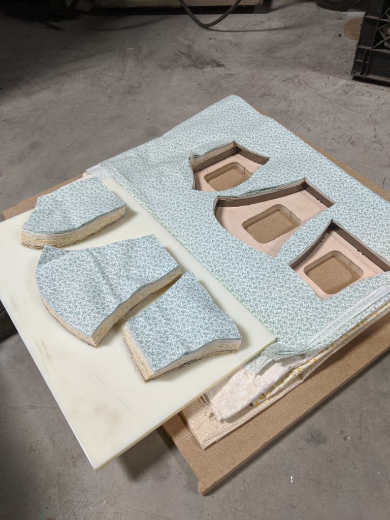
Thanks to a generous die donation by Plastic Ingenuity we have a die cut pattern for Olson face masks as well as square masks (that require two 9″x4.5″ and one 9″x7″ pieces). Many thanks to our SASY Neighborhood Association for sponsoring this Dane County Mask Makers to purchase more materials and elastic – please reach out to them directly to request mask donations.
We’ve cut over 15k+ mask patterns so far!
If you’re interested in having us cut material for you we need you to prepare it so we can cut it quickly:
Please prewash and dry (shrink) your fabric so the size won’t change when it is washed (if you don’t mind, we don’t need it prewashed)
The die will cut one pattern for both sides, if you’d like correct patterns out for both sides then you must fold the material at least once so it’s back to back or face to face when it goes into the cutter (this will make mirrored cuts)
Prepare your fabric into 10″ x 20″ rectangles, these can be individual layers or Z-folded material in as many layers as you can stack
Please make sure your material is flat, the knife will cut straight down through a fold/etc meaning the size will be wrong if it’s folded or bunched. Ironing is not necessary as long as it lays flat.
Coordinate with the e-mail address above to drop off material. We can cut it while you wait if you’ve prepared it correctly, we just need to know which pattern you want
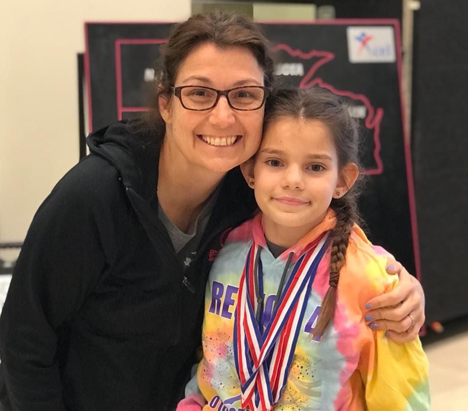
It’s with great sadness that I write this, but it’s important we thank those who impact our entrepreneurial community in Madison in such major ways- thank you Amy for the work that you’ve done. We’ll miss you – and we’ll do our best to carry forward as you would have wanted.
I think a little history here is important, a thank you means a lot more with context and perspective so I hope you’ll bear with me.
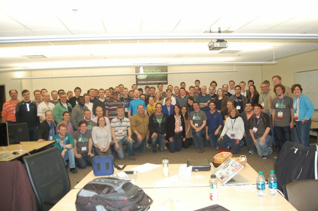
My introduction to Amy was through Lorin Toepper, then the executive director of economic development at Madison College who we also lost so early in his career. Lorin’s goal was to draw together entrepreneurial innovators in the city and host a “Startup Weekend” and Amy was first on the list. Startup Weekend itself was just a startup then, Lorin found a concept that was way ahead of its time and worked hard to bring us together and make it happen – once this was in front of Amy it wasn’t a question of whether it would happen, just a matter of when. Her spirit and can-do regardless of the obstacles was what made working with Amy interesting and fun, and she knew it. Practically the next day, Amy had her husband Mike roped in to drum up some PR and there was no turning back.
Ultimately, Startup Weekend drew Amy, Lorin, Forrest Woolworth, Allen Dines, and I together and solidified an event that still happens every spring – many thanks to organizers who have stepped up to carry forward when those of us were unable. Without Lorin’s leadership and Amy’s enthusiasm our city wouldn’t be shaped the way it is today – Startup Weekend created a lot more startup’s than any of us realized: When I met Amy, I realized I needed to introduce her to Heather Wentler – I think their shared love for teaching instantly connected and they grew from there. Amy and Heather both saw something the Madison community didn’t – a lack of women and minority involvement in entrepreneurship. Rather than be content with this, they talked at length during the inaugural Startup Weekend and created a “Women’s Entrepreneur Group” by mid-2012 – action was Amy’s way forward on anything she felt was worth pursuing. Heather and Amy have moved The Doyenne Group miles forward over the past 7 years. I hope our community steps up to help carry forward this important work – Amy leaves behind big shoes to fill and I hope we’re ready to step into them and keep working forward.
The business incubator at Sector67 has a new member: John Lash started Mad DesignWorks LLC there in September of this year. Focused on designing and building custom assistive and adaptive devices for the disabled community Sector67 with its combination of office space and well appointed shop space is the perfect fit for a small startup like Mad DesignWorks.
After graduating from Madison College with a degree in Mechanical Design John wanted to do something to make the world a better place. Combining his interest in assistive and adaptive devices with his interest in design John aims to improve the quality of life for people with physical disabilities.
In addition to building custom assistive and adaptive devices Mad DesignWorks offers a variety of other services including:
Modification of existing equipment
Fabrication of hard to find or obsolete replacement parts
Modification of furniture
Consulting
504 Plan compliance
Design and Manufacture of ergonomic devices
Helping employers meet the needs of all their employees
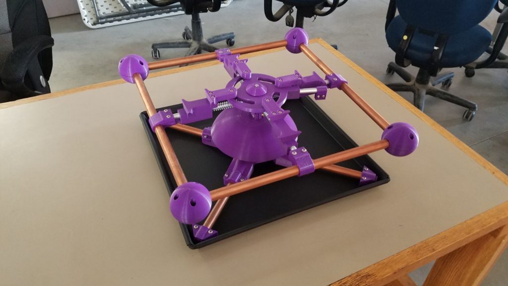
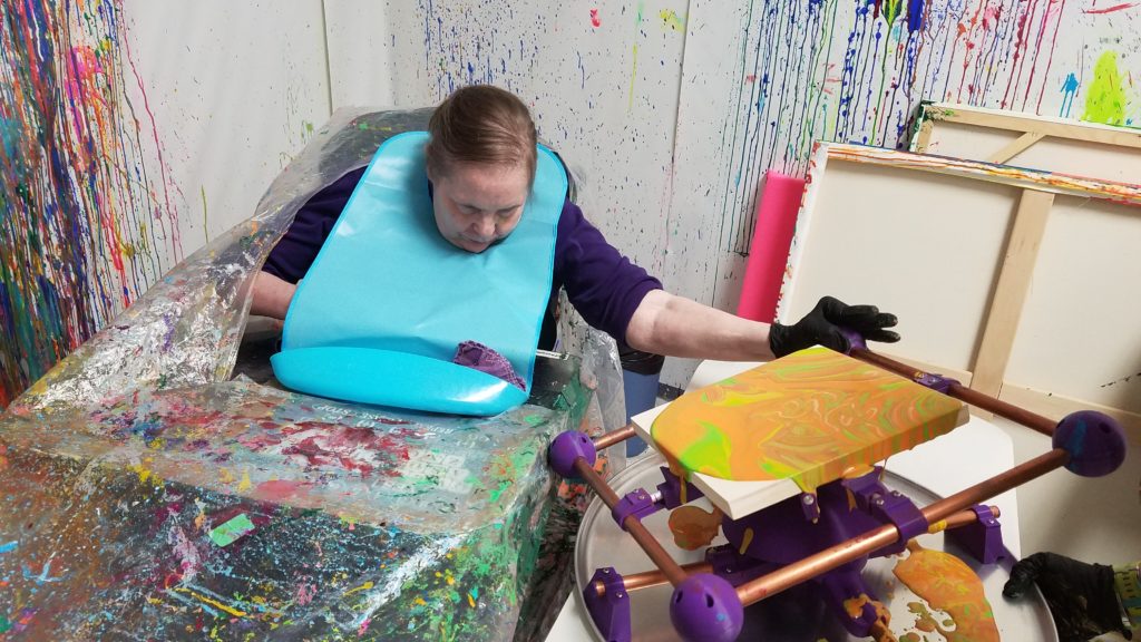
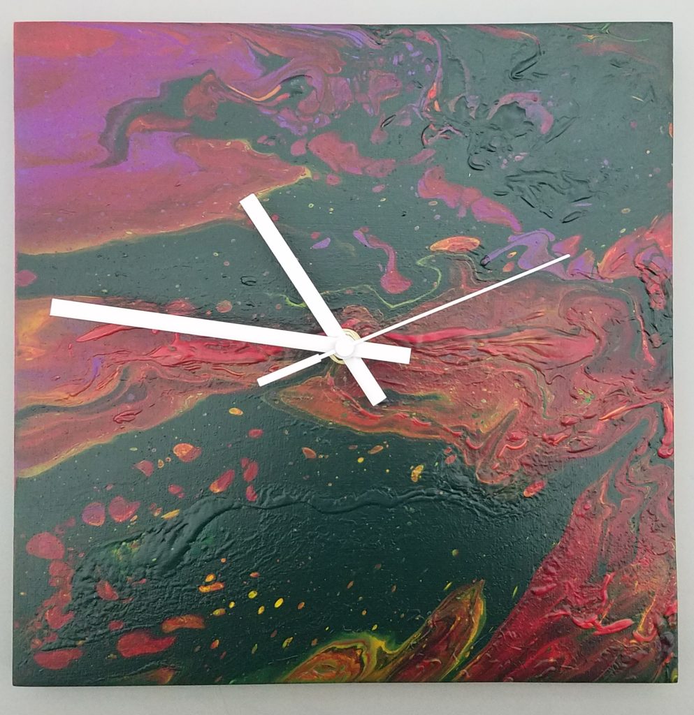
One of the first projects Mad DesignWorks did at Sector67 was to design and build a custom tilt table to help a client with only limited use of one arm to pursue her painting career. With her new tilt table Jeanne can paint more independently than ever before. Once Jeanne is finished with a painting it is turned into a clock and sold locally.
The completed tilt table.Jeanne painting with her new tilt table.The final product.
Helping people like Jeanne become more independent and self supporting is really why Mad DesignWorks exists. Without the support of Sector67 and Chris Meyer this would not be possible, Mad DesignWorks is proud to be a part of this community.
To contact Mad DesignWorks LLC please call or text:
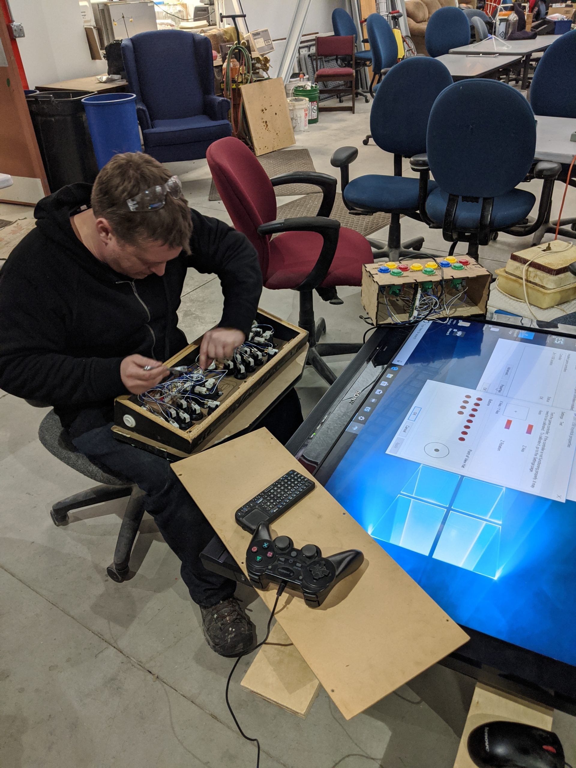
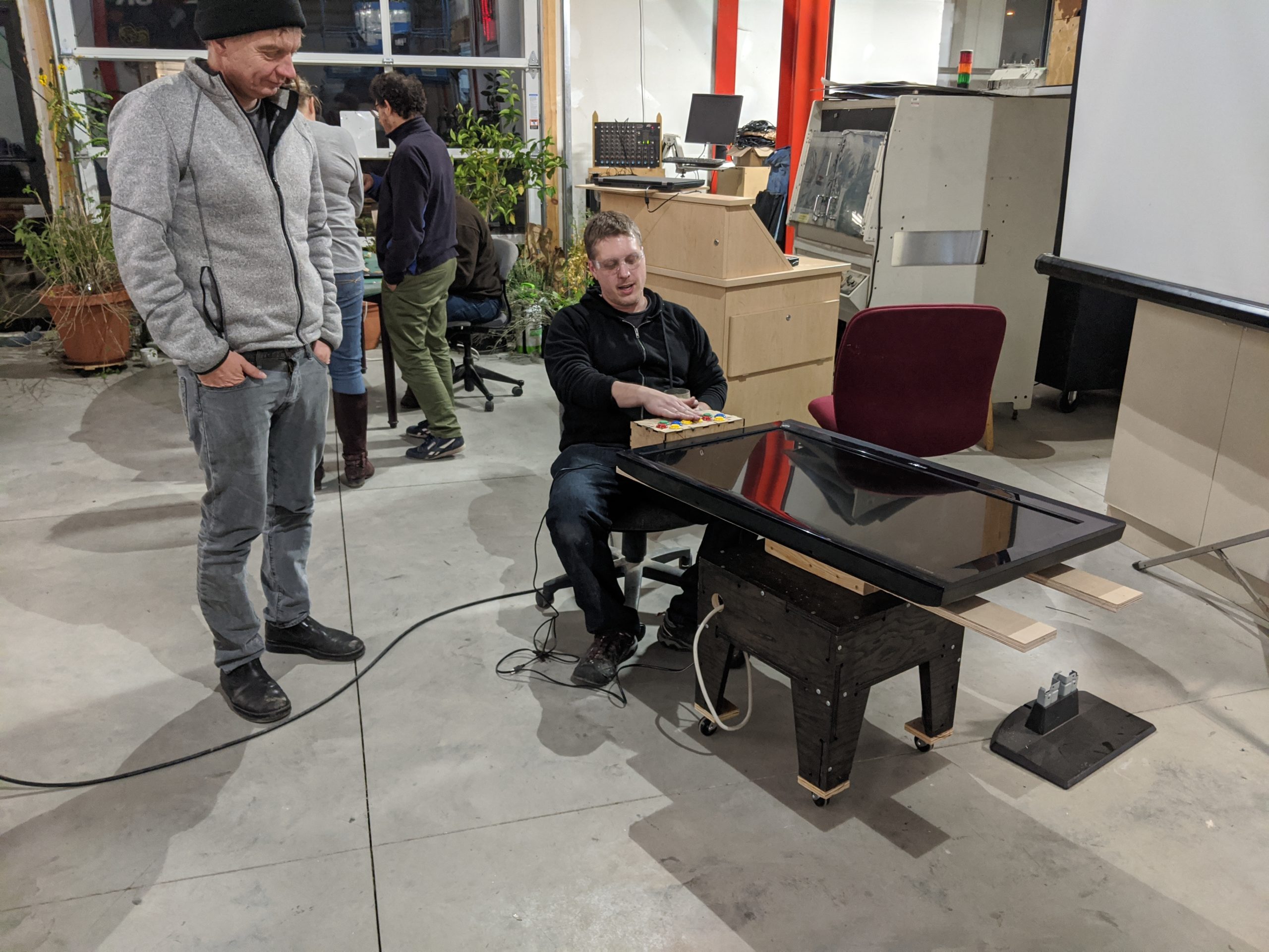
2019’s Build Madison kicked off on a bright and warm November day with a wide variety of projects:
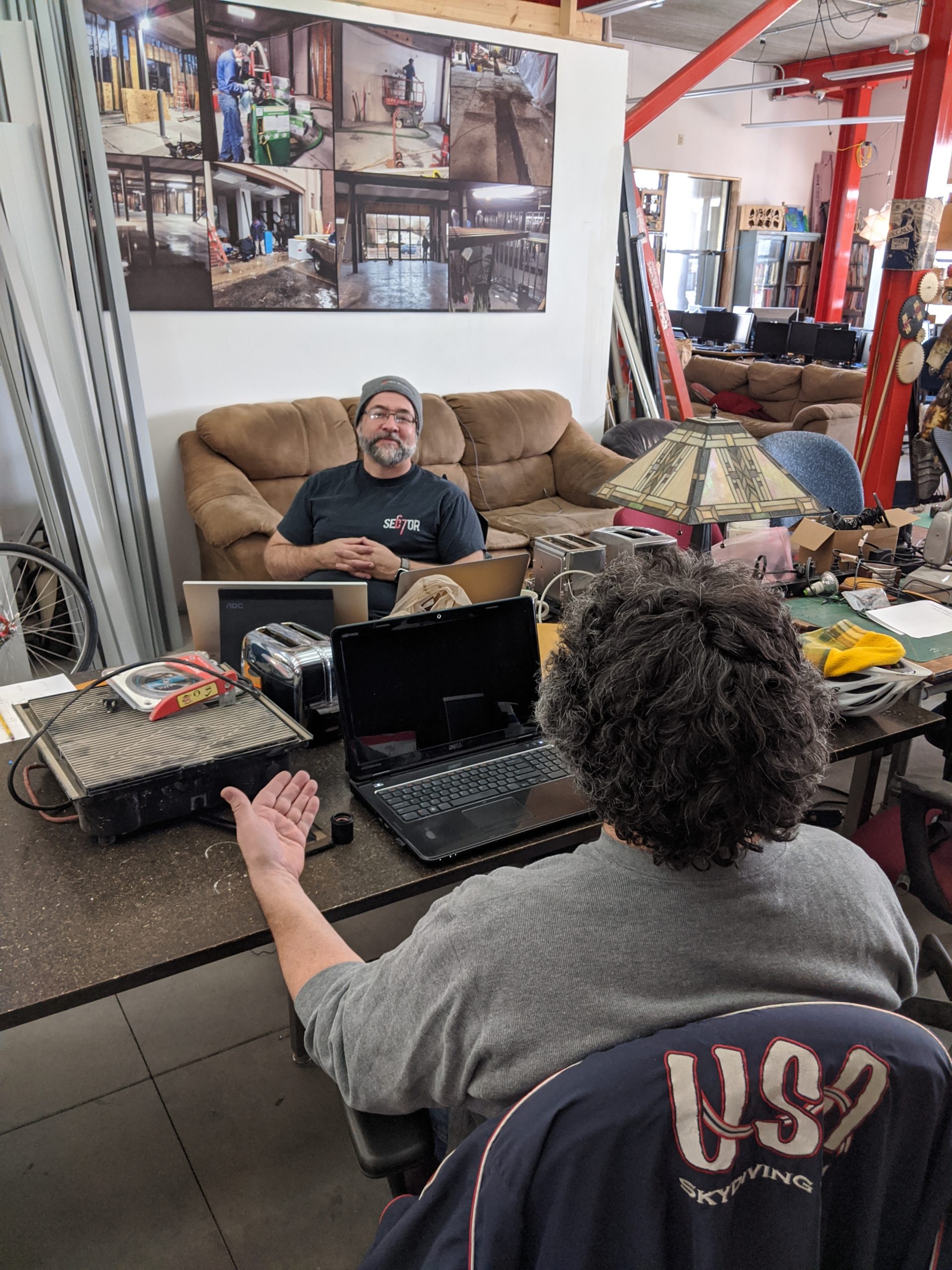
Scott – Moved forward on the open toaster project – the goal being to create a maintainable open-source appliance that never becomes obsolete, starting with the toaster.
Brian – Built a cocktail table MAME (classic arcade) cabinet using the wood shop and laser cutter to create a TV stand as well as button interface.
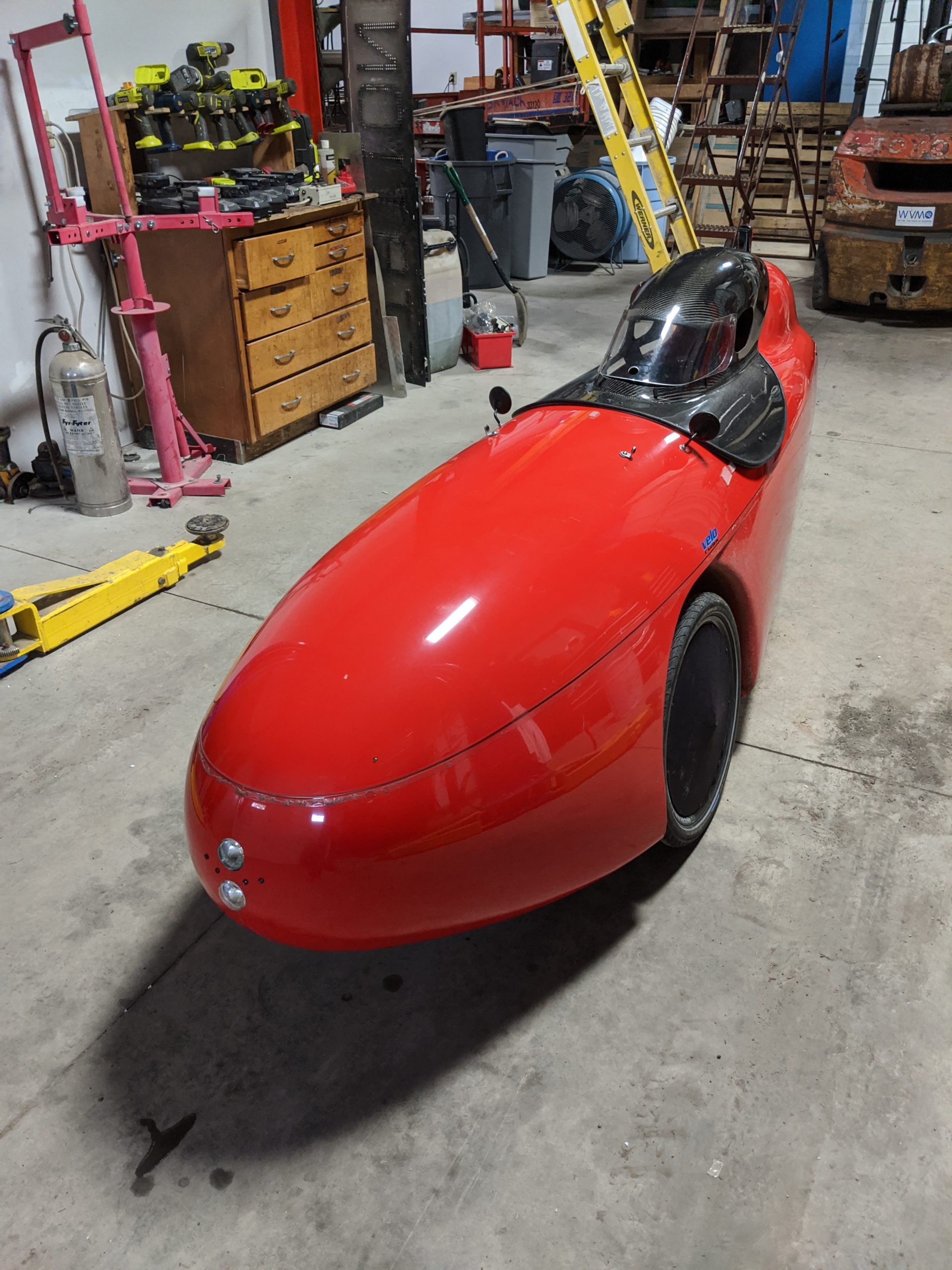
Jim and Nick – Continued efforts on an enclosed bicycle transmission that keeps the geartrain out of the weather and debris. (and the velomobile needed a light and horn adjustment)
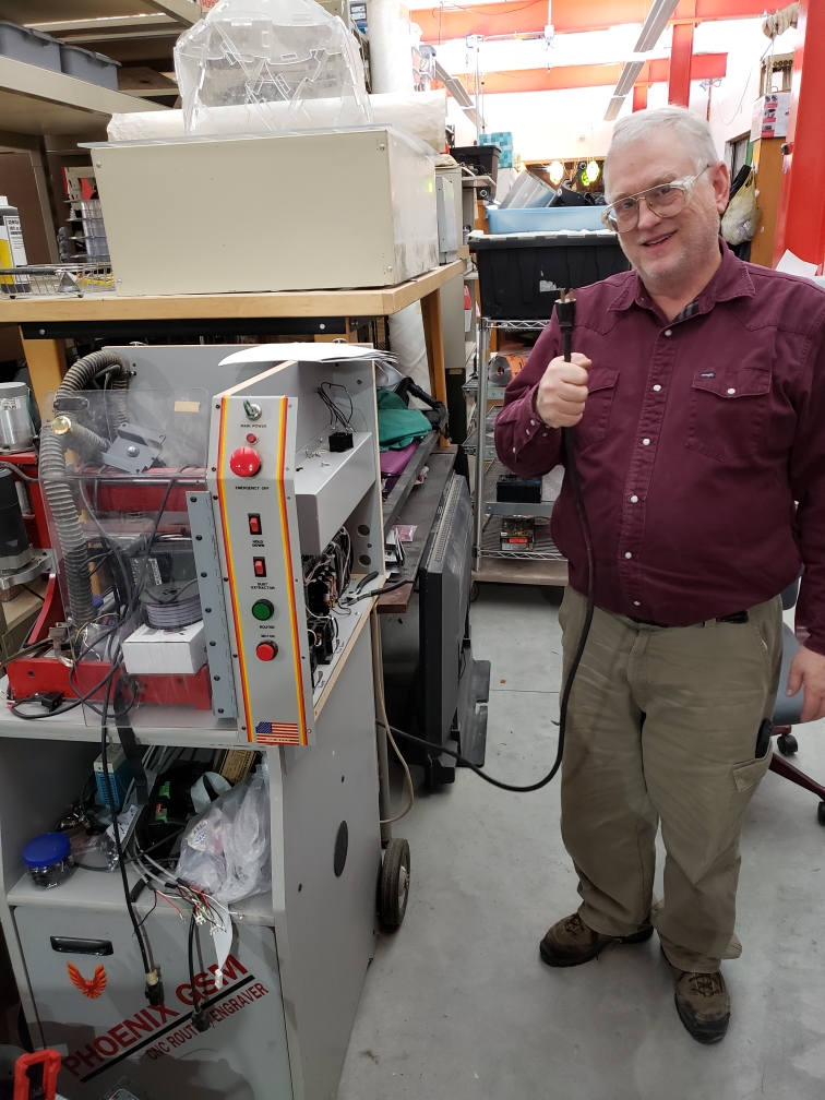
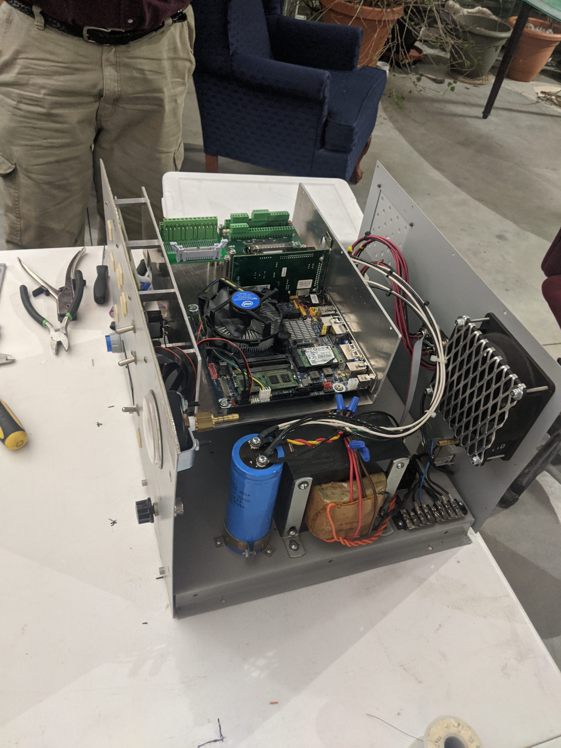
Brian – Refit an old Phoenix GSM enclosed CNC wood router with LinuxCNC.
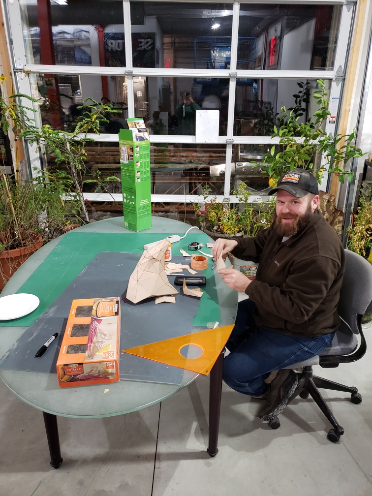
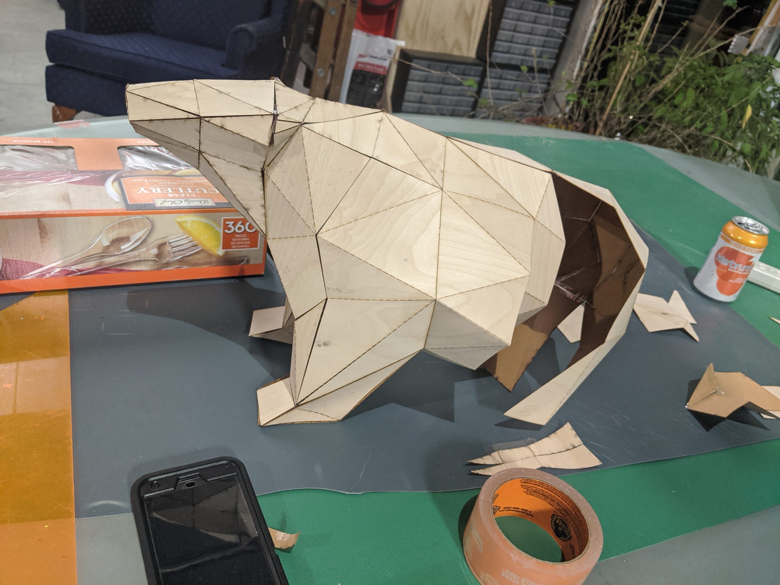
Chris – Used the laser cutter to build a papercraft polar bear with paper-backed wood veneer.
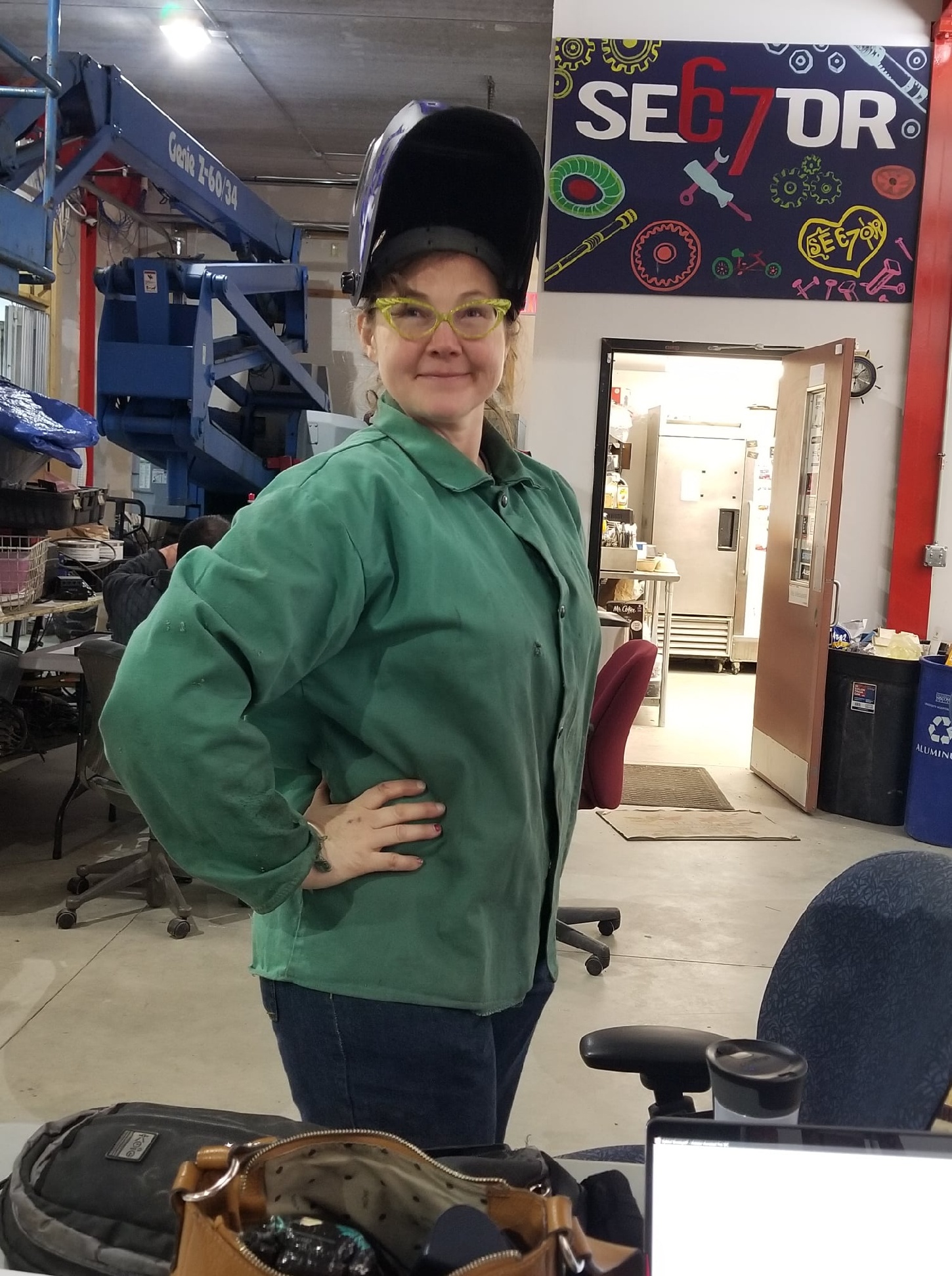
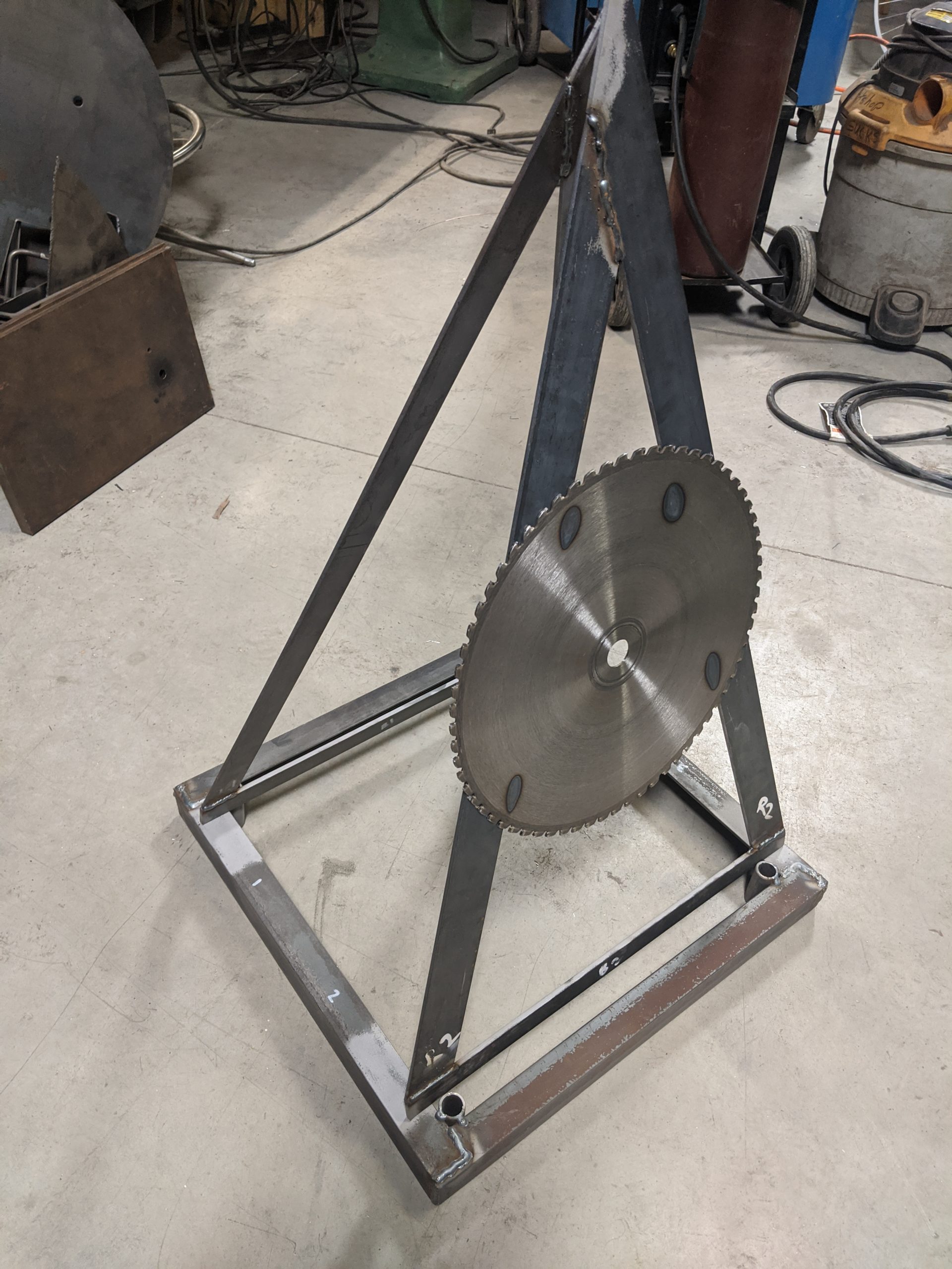
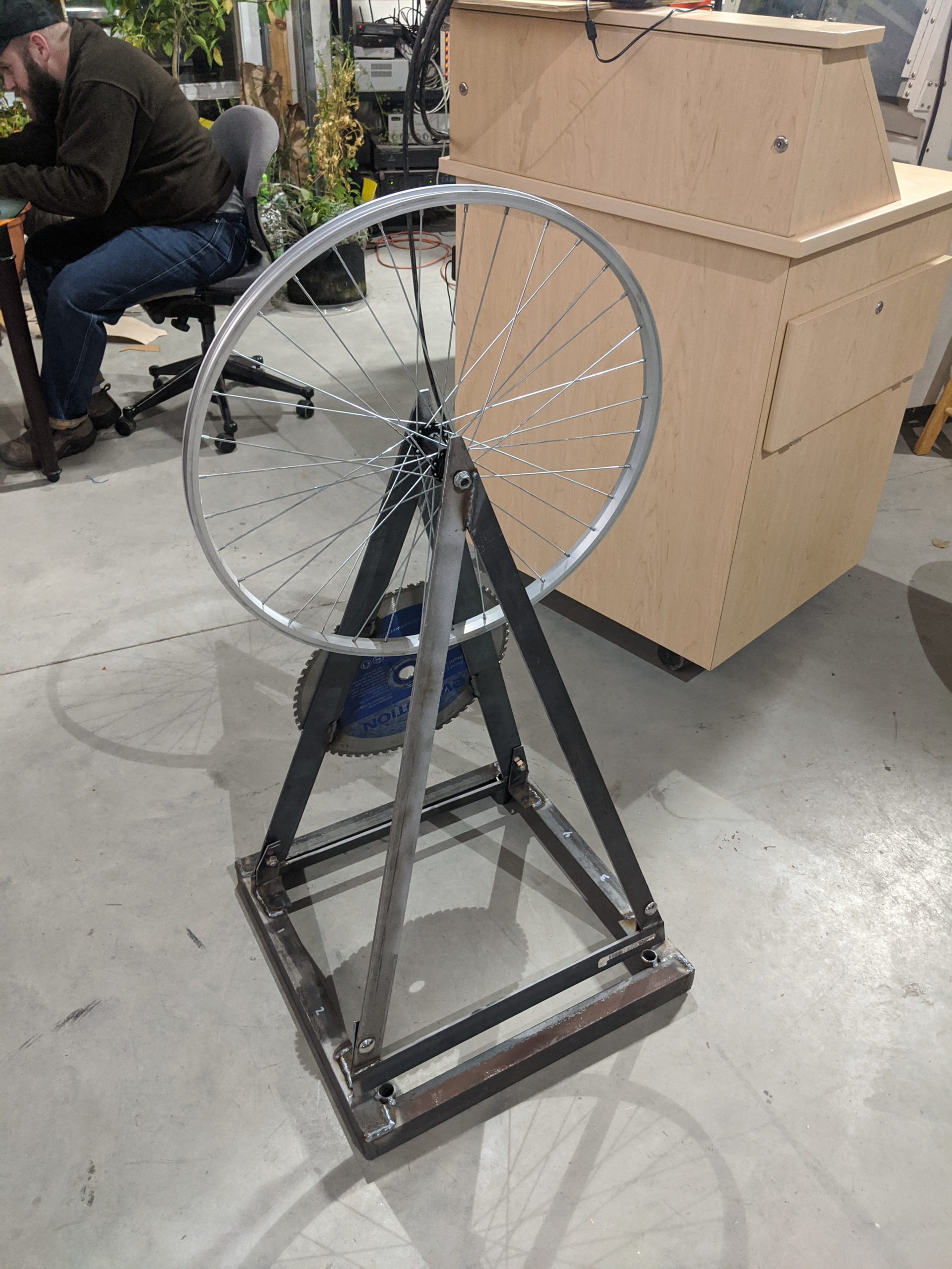
Laima – Created a steel kinetic yard art sculpture using bicycle parts and stained glass (future work!).
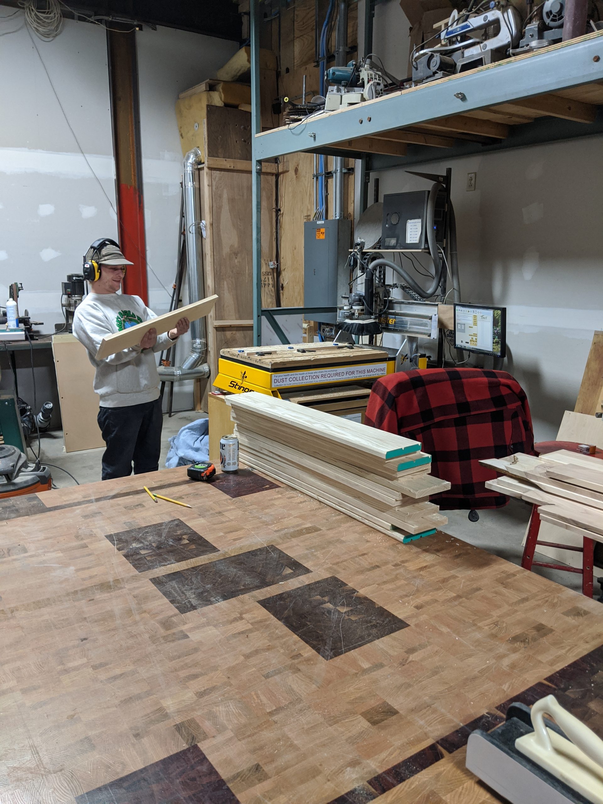
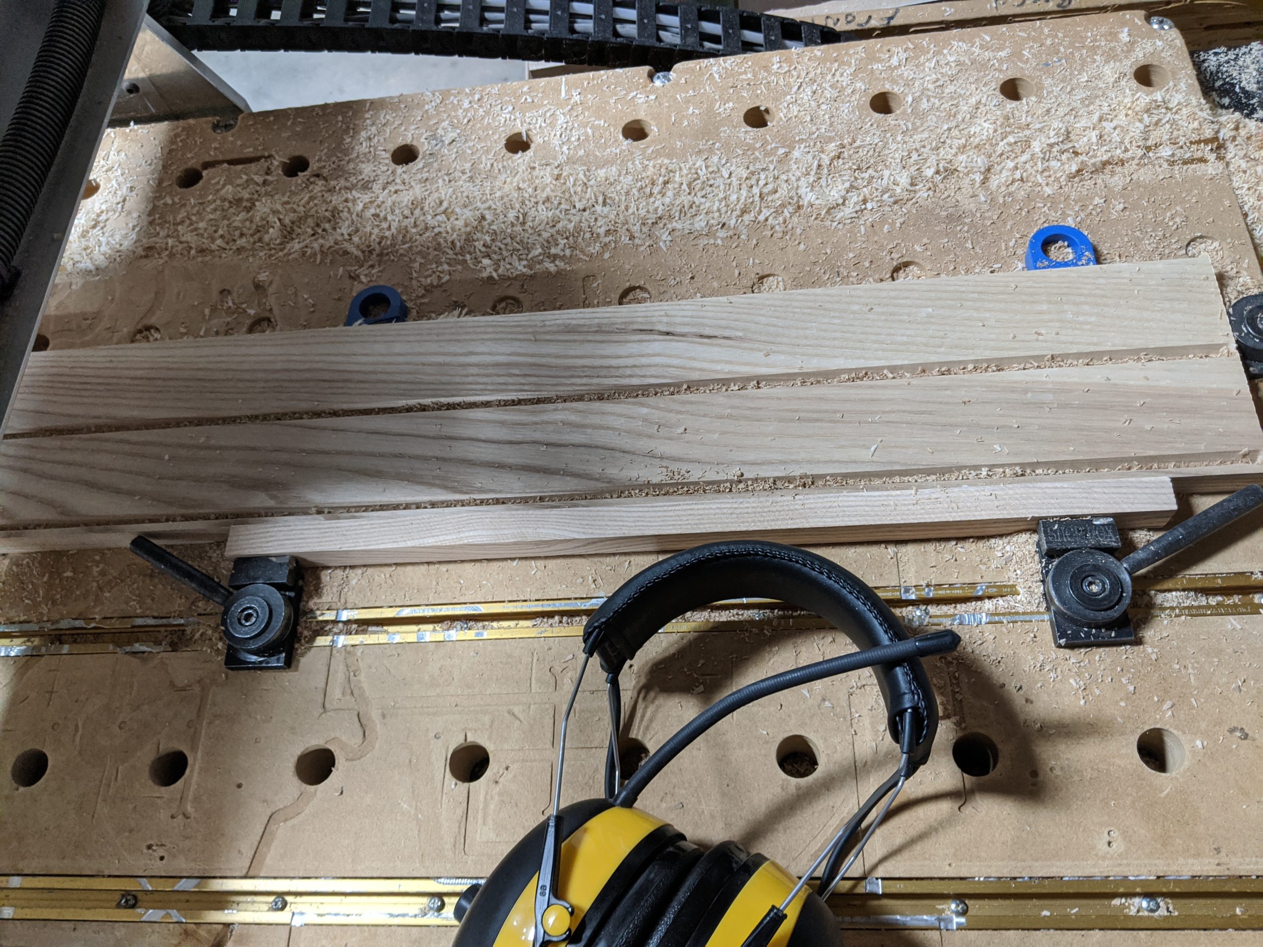
Adam – Made ash trim for the face of a sink base cabinet using the CNC router and a v-bit.
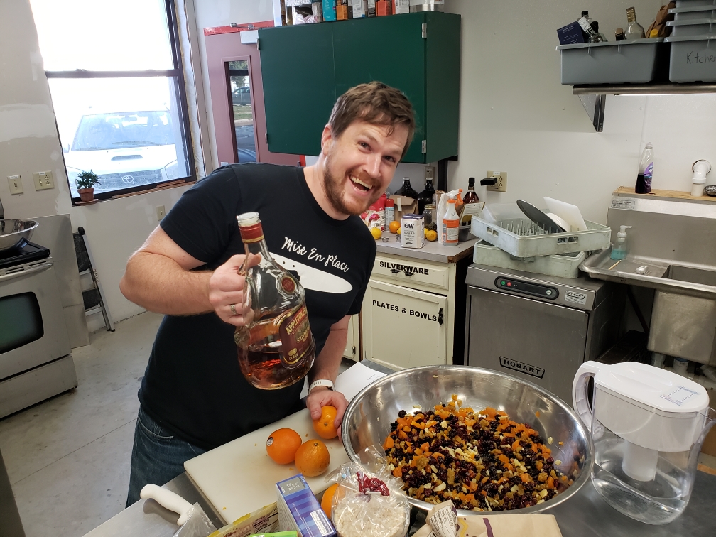
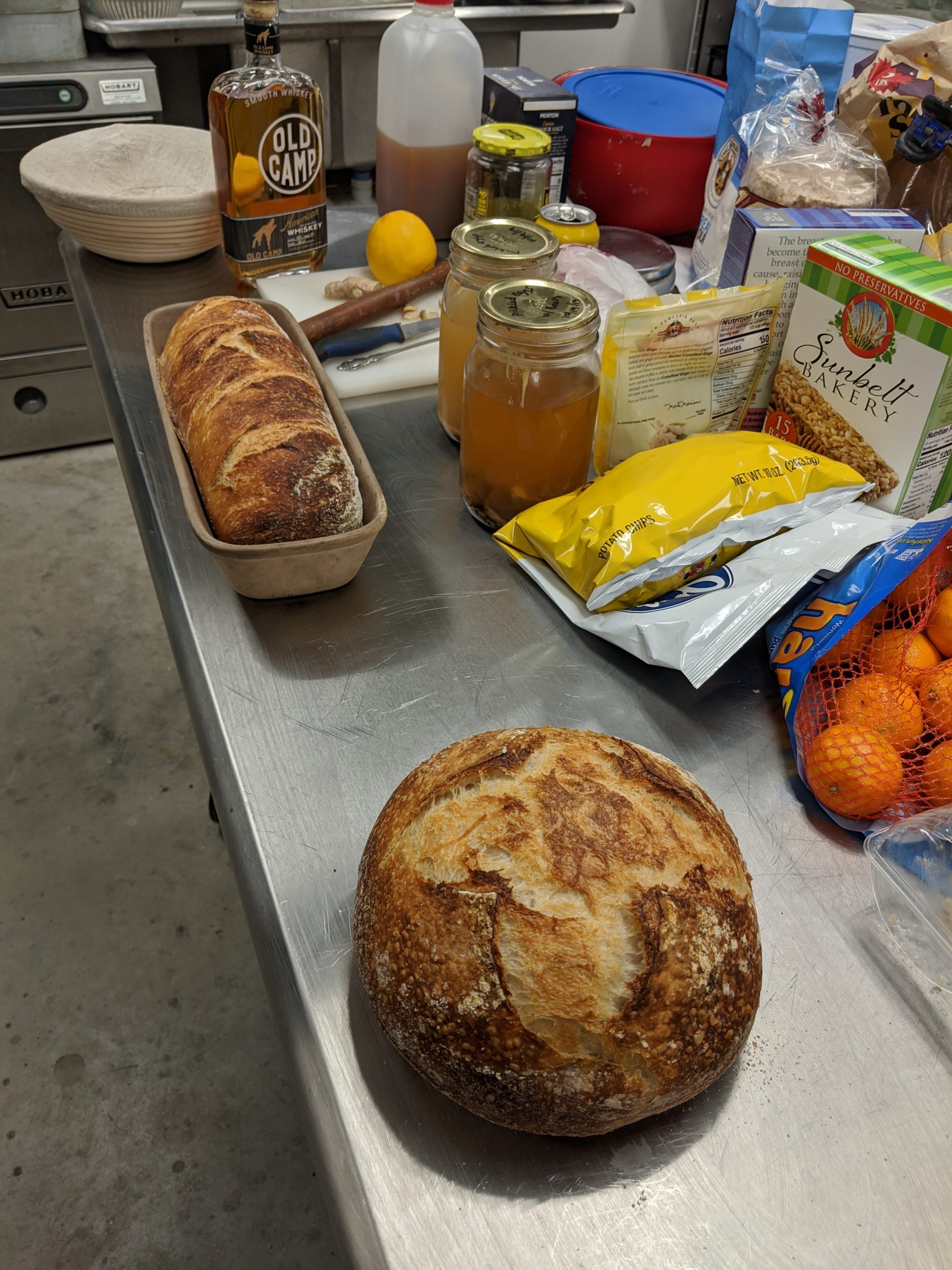
Jeremy – Baked 3 loaves of Jeremy’s Special Sour Dough [JSSD ™] bread and a “fruit cake so nice that you’d want to receive it as a gift”
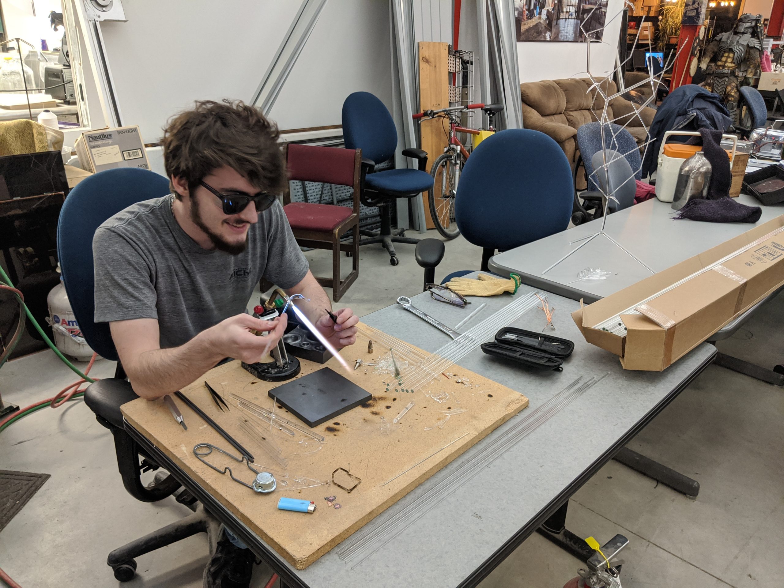
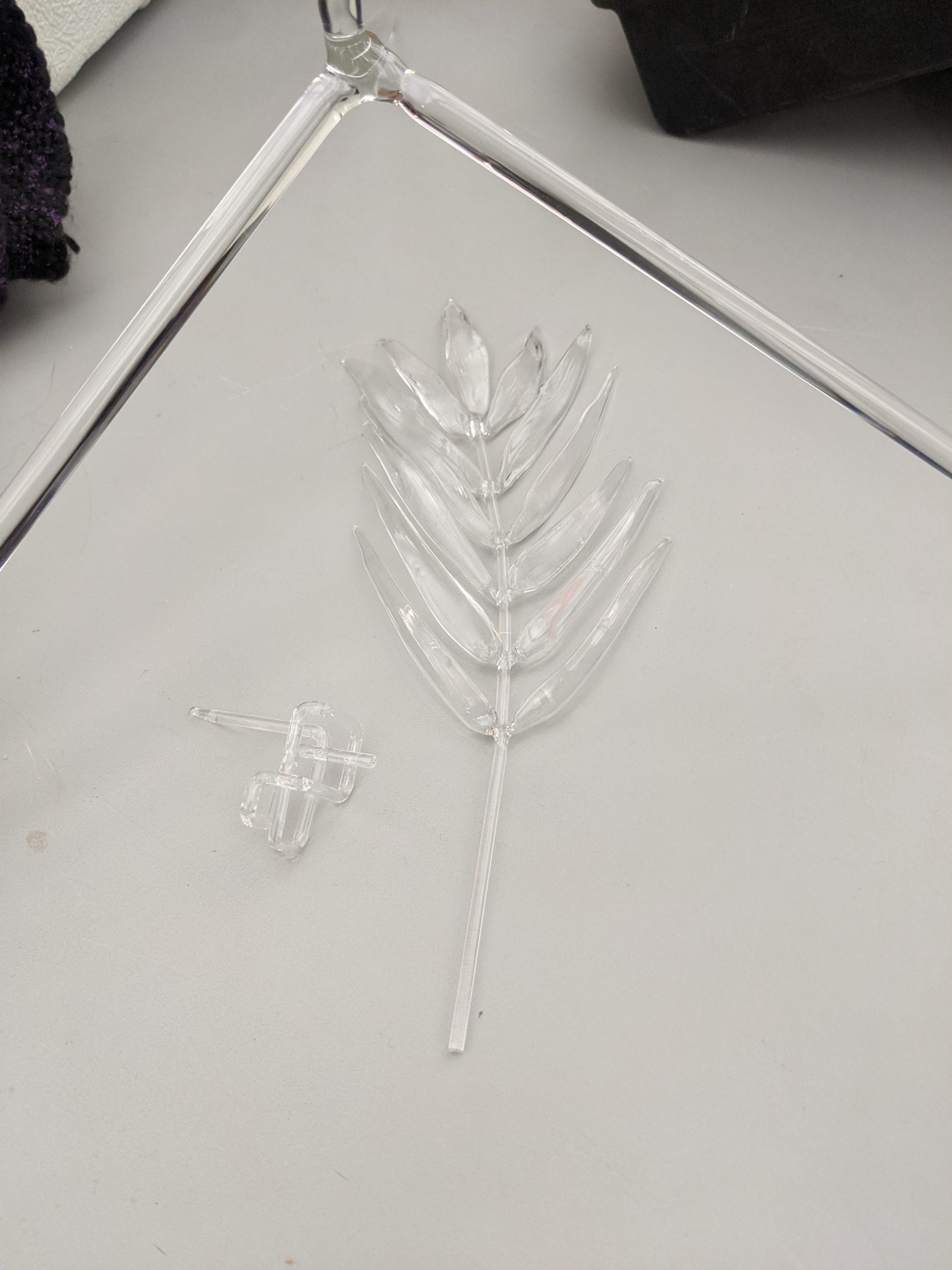
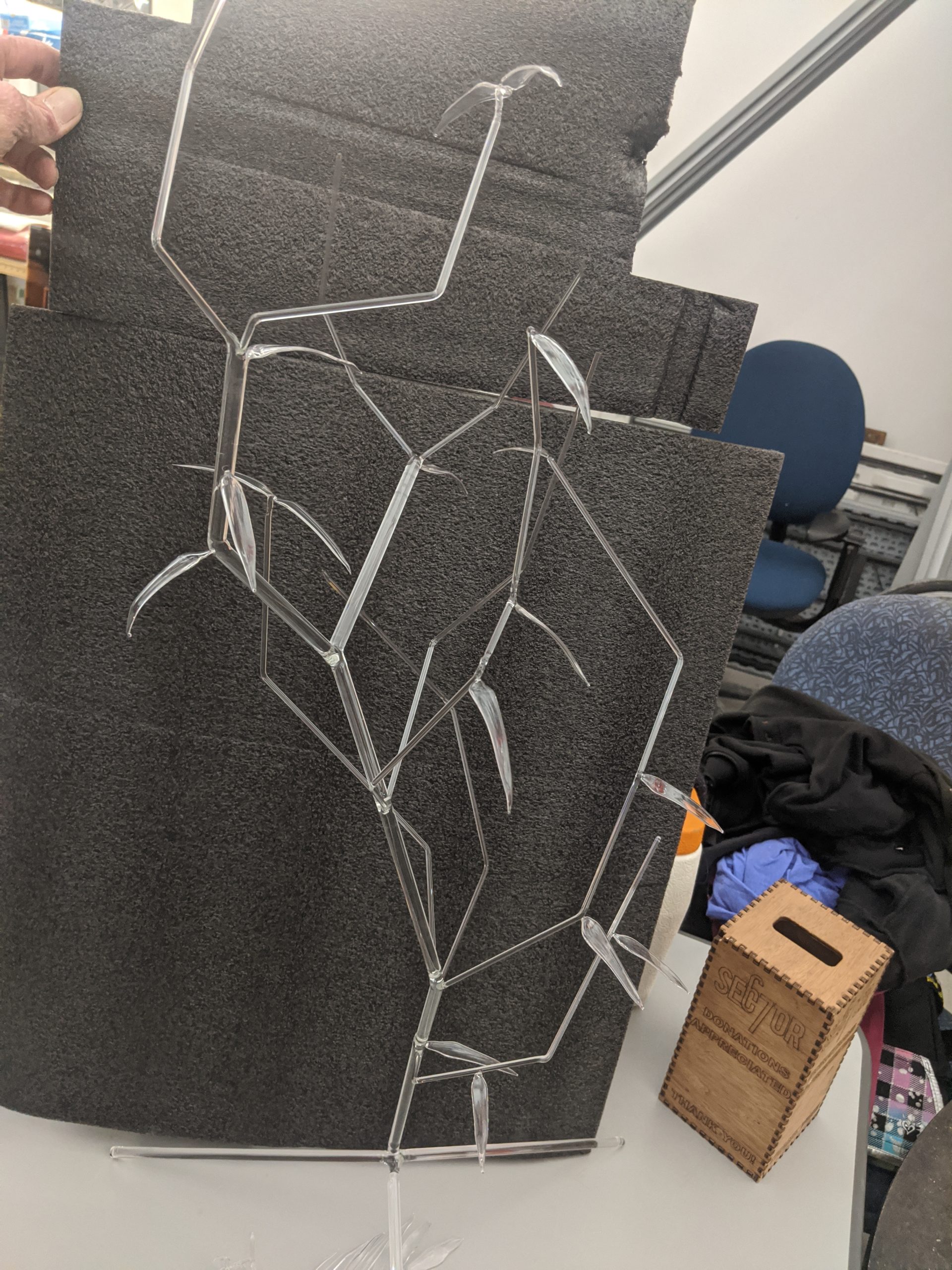
Max – Tested his glass lampworking skills by building a plant inspired glass piece with realistic leaves and branching structure from borosilicate glass rod.
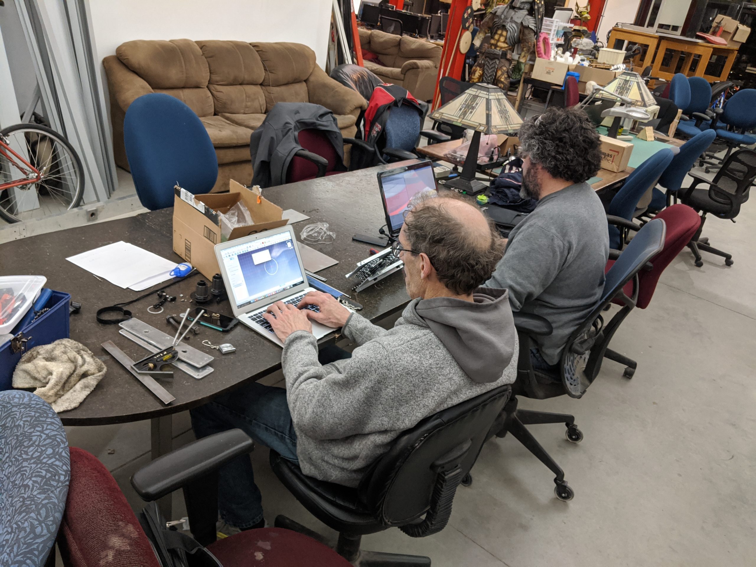
John – assisted a few people with design and engineering advice
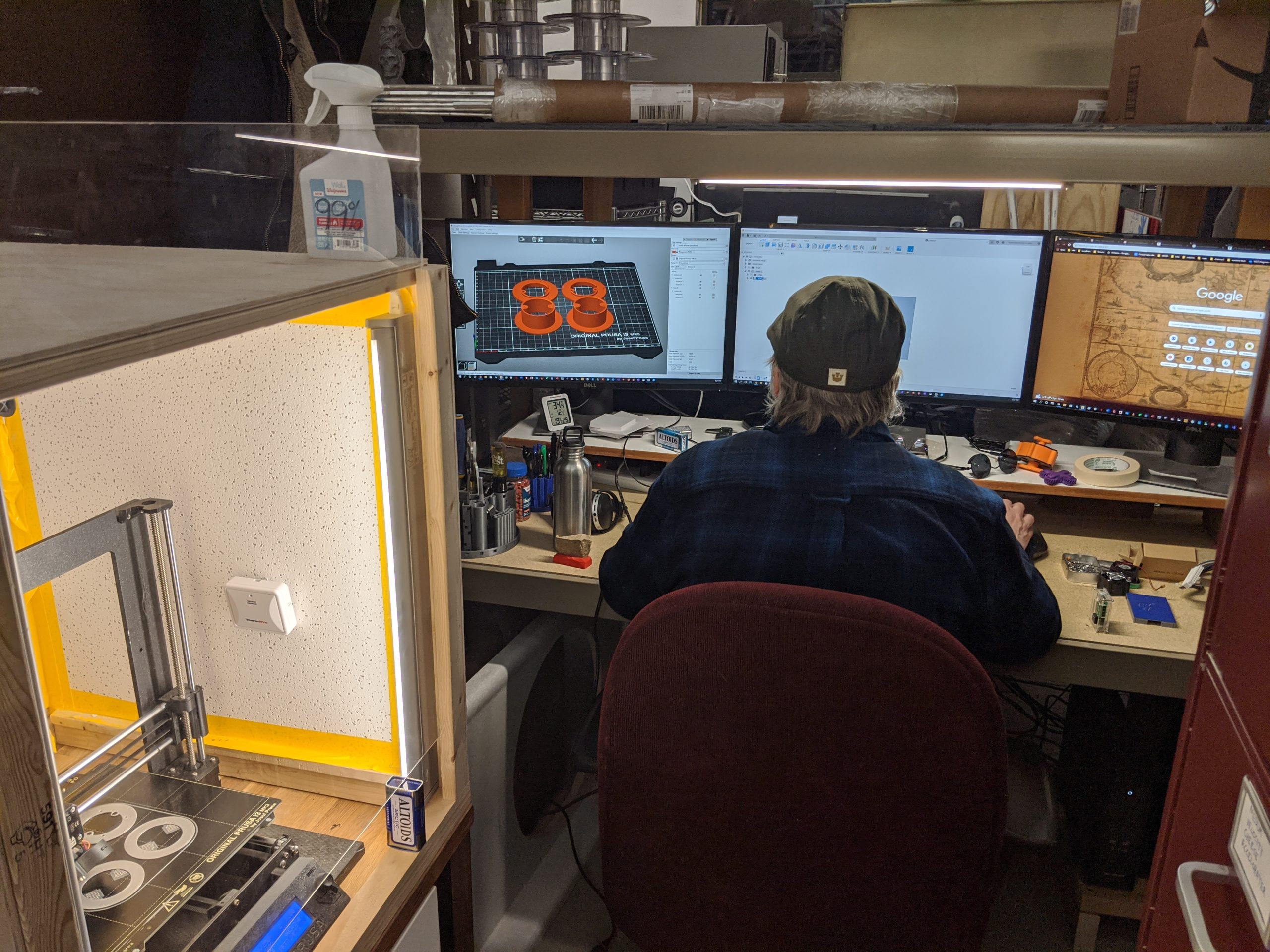
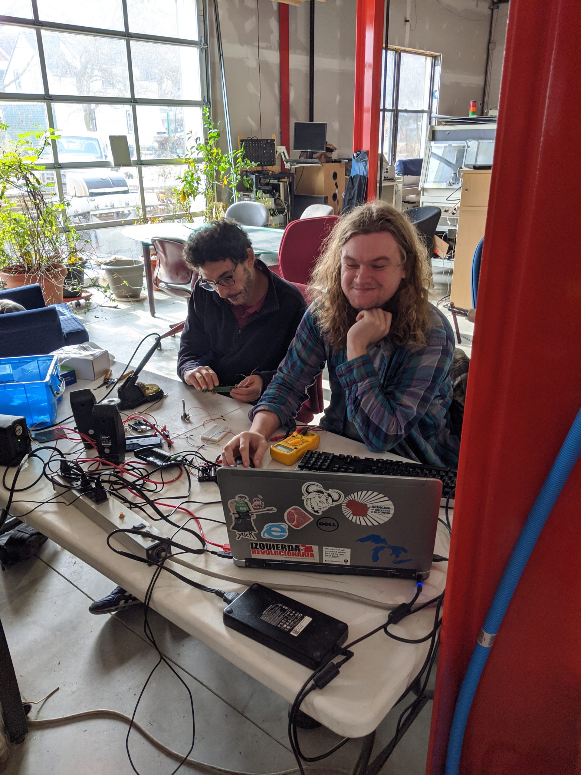
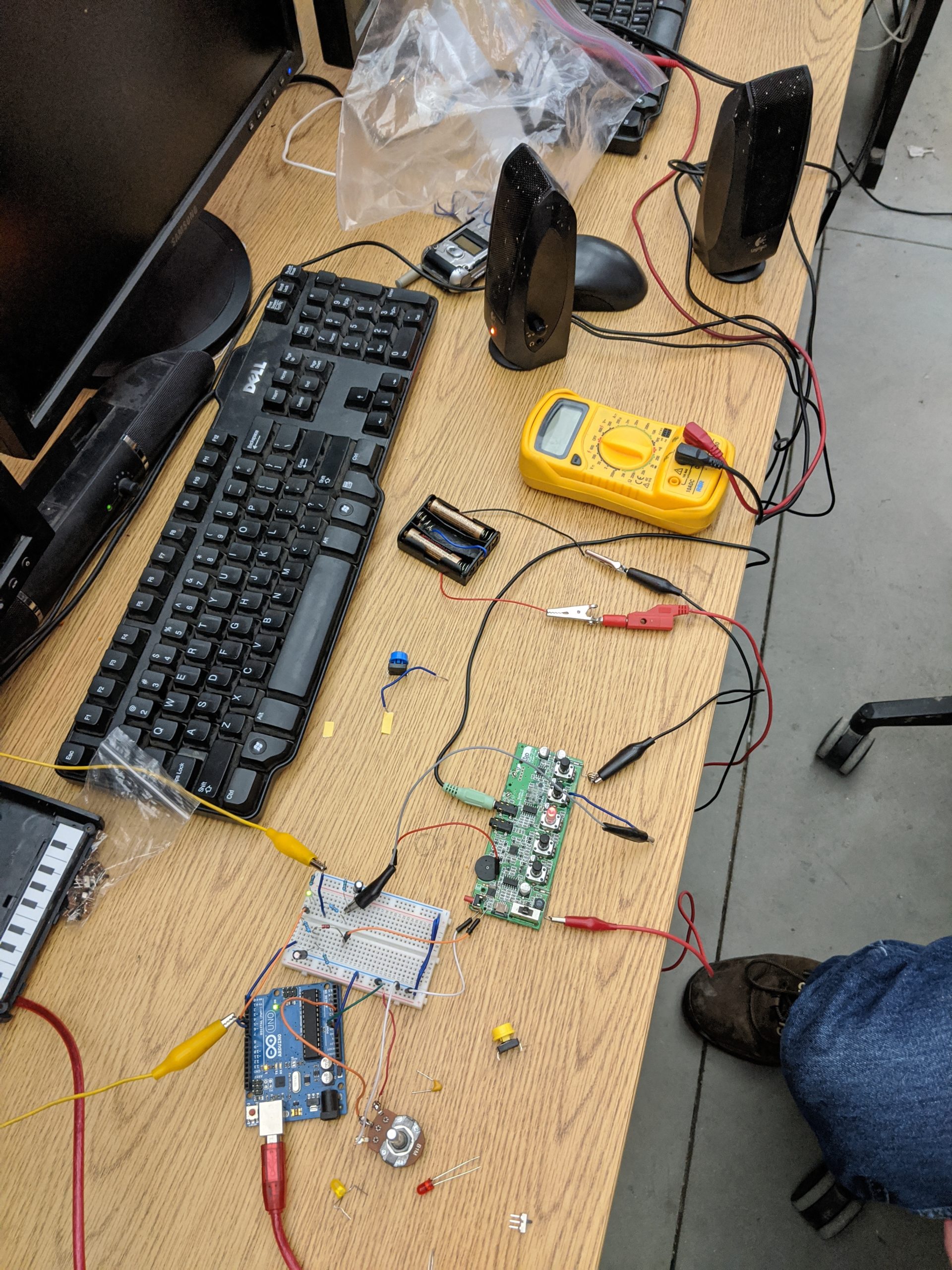
Jack and Davi – Modified a Korg Monotron Synthesizer to run from an Arduino to enable digital and preprogrammed effects.
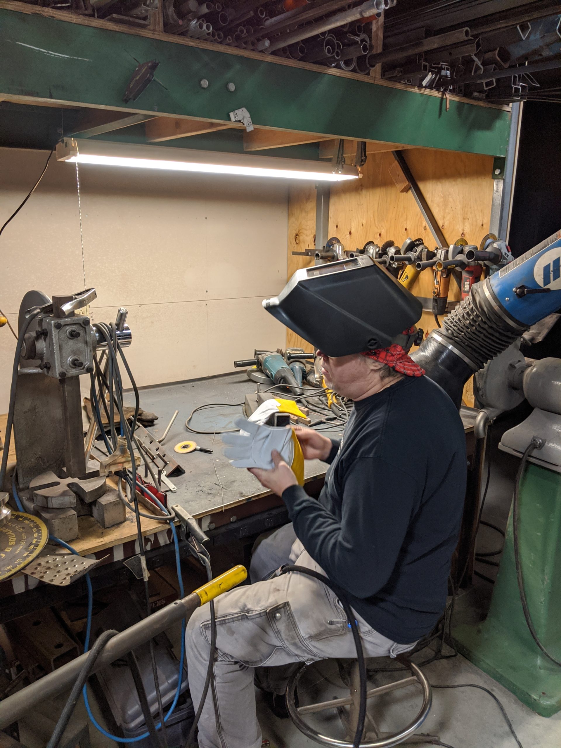
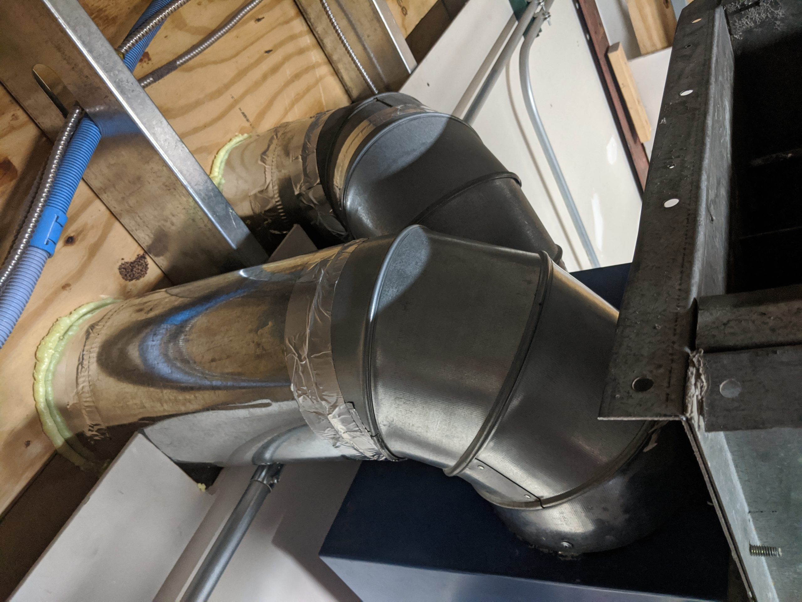
Chris – Wrote a summary blog 🙂 and finished construction on the exterior exhaust and ductwork (thanks Nate!) for the welding shop air filtration system.
Participants enjoyed a late breakfast of pie and snacks, brats and hamburgers for lunch, pizza for dinner, and handmade pancakes for breakfast. Hope you can join us next year for 2020!