Product Description
1 Description
The heart of b2Flex is a Microcontroller (uC) that contains the user interface firmware. Features of
this circuit/UI combination include:
• Choice of 3 different User Interfaces, UIF fixed lighting optimized, UIP portable lighting
optimized and UIB2 bicycle lighting optimized.
• High efficiency Buck mode (step down) switching regulator (maximum drive current set in
firmware).
• Single switch to select from various brightness levels, turn the unit on/off, select the
operating modes and set menu options.
• Non-volatile (EEPROM) storage of operating mode, last selected brightness level, and
maximum drive level (350mA, 500mA, 750mA, 1000mA, 1200mA or 1500mA).
• Voltage sensing with three user configurable trip points for ½ discharged and nearly fully
discharged and forced off (or warn only). Warning display via an optional 3mm or 5mm
status LED or via the main LED.
• Temperature sensing with user configurable trip point to limit output current to protect the
driver and/or LED.
- b2Flex.pdf (V1.0, manual for b2Flex V1.0 – UI-UNI2 firmware)
Efficiency Measurements:
As with any buck driver, efficiency is highest when input voltage is closer to output voltage and also with higher voltages. So, a 1 LED (3.3V Vf) system will be less efficient than say a 3 LED (10V Vf) system.
Typical measured efficiency values are shown in the table below
| # LEDs | Input Voltage | Output Current | Efficiency |
|
1
|
4V
|
350mA
|
87%
|
|
1
|
10V
|
350mA
|
80%
|
|
1
|
14.8
|
350mA
|
76%
|
|
2
|
8V
|
500mA
|
91%
|
|
2
|
14.8V
|
500mA
|
88%
|
|
2
|
8V
|
750mA
|
91%
|
|
2
|
14.8V
|
750mA
|
89%
|
|
2
|
8V
|
1000mA
|
90%
|
|
2
|
14.8V
|
1000mA
|
89%
|
|
2
|
8V
|
1200mA
|
90%
|
|
2
|
14.8V
|
1200mA
|
88%
|
|
2
|
8V
|
1500mA
|
88%
|
|
2
|
14.8V
|
1500mA
|
87%
|
|
3
|
11V
|
350mA
|
92%
|
|
3
|
14.8V
|
350mA
|
88%
|
|
3
|
11V
|
500mA
|
93%
|
|
3
|
14.8V
|
500mA
|
91%
|
|
3
|
11V
|
750mA
|
92%
|
|
3
|
14.8V
|
750mA
|
91%
|
|
3
|
11V
|
1000mA
|
92%
|
|
3
|
14.8V
|
1000mA
|
91%
|
|
3
|
11V
|
1200mA
|
91%
|
|
3
|
14.8V
|
1200mA
|
90%
|
|
3
|
11V
|
1500mA
|
90%
|
|
3
|
14.8V
|
1500mA
|
89%
|
As can be seen from the table, in a 3 LED, 4 Li-Ion system, the b2Flex will be typically running around 90% efficient.
So, assuming 3 LEDs with a total Vf of 10.5V at 1500mA we can calculate driver power dissipation as:
10.5V x 1.5A x 0.1 = 1.6W
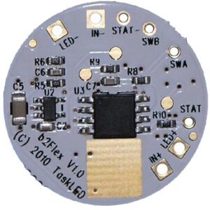
It is HIGHLY recommended that the b2Flex be attached to a heatsink/thermal path using the gold rectangular area in the following picture.
Potting Warning:
Areas of the circuitry on b2Flex utilize high impedance paths and if potting (not required) is to be utilized, the user must ensure than the compound is non-conductive and non-capacitive otherwise correct operation may be compromised. A product like Artic Alumina epoxy will work well.
The following picture shows the top of b2Flex.
The X/Y position of the various solder pads/connection points is in the table below. X/Y position 0,0 is the center of the board. X/Y positions are in mils (0.001″, so -230 means -0.230″)

|
PAD
|
X
|
Y
|
| LED- | -230 | 360 |
| IN- | -40 | 415 |
| STAT- | 95 | 415 |
| SWB | 220 | 360 |
| SWA | 340 | 245 |
| STAT | 405 | -100 |
| LED+ | 355 | -225 |
| IN+ | 270 | -330 |
Input voltage connects to IN+ and IN-.
The LED(s) connect to LED+ and LED- (NOTE: LED- is NOT the same as IN-).
The control switch connects to SWA and SWB (SWB is electrically the same as IN-). The switch only switches a control signal and carries at most 350microamps.
The status LED (optional) connects to STAT and STAT- (STAT- is electrically the same as IN-).
The following picture shows the bottom of b2Flex.

Cost here includes all taxes, local pickup only on tour days or please schedule a pickup time via the contact us link at the top right.


